JOHN SEFTON’s first scratch built model
Why choose the Edmund Gardner?
For over thirty years I worked for the Mersey Docks and Harbour Board and spent much of that time travelling to and from work on the Mersey Ferries. This gave me ample opportunity to view the shipping on the Mersey, including such vessels as Reina del Mar, Aureol and the Empress liners. What great memories!
Enjoy more Model Boats Magazine reading.
Click here to subscribe & save.
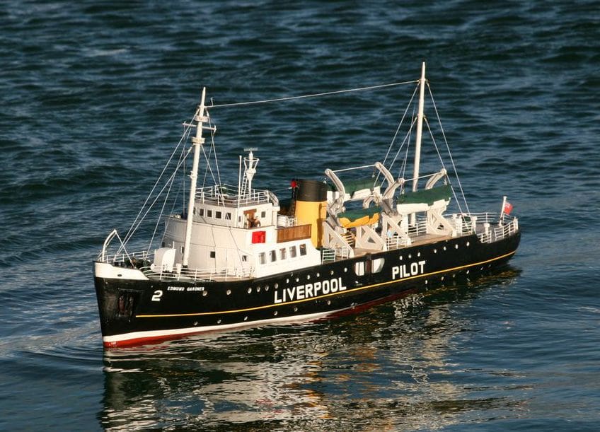
A vessel that I had always particularly admired was Edmund Gardner, Liverpool Pilot Cutter No. 2. To me, she made me think of a millionaire’s yacht with her graceful lines, although millionaire’s yachts have changed in recent times, so what better reason then for me to make as my first scratch build a model of Edmund Gardner?
The ship’s pedigree
Edmund Gardner and her two sister ships were designed by naval architects Graham and Woolnough of Liverpool. She was built in Dartmouth by Philip and Sons Ltd, launched in July 1953 and was in service as a pilot vessel from December of that year until April 1981, when she was one of the last two remaining large cutters on duty. Following tradition, all three were named after a Chairman of the Board, the other two being the Sir Thomas Brocklebank (No. 1) and Arnet Robinson (No. 3). The Merseyside Maritime Museum purchased her in 1982 and she is now conserved in dry dock and open to the public during the summer. Many of her features, for example the control and navigation equipment on the bridge, parallel typical equipment on larger 20th century merchant ships.
Starting the build
I obtained the builder’s plans from the Merseyside Maritime Museum, and as the ship is preserved in the graving dock by the museum, I was able to take a plentiful supply of photographs. The full size vessel is 54.1m long, with a beam of 9.6m, draft at the stern of 3.7m and GRT of 701 tonnes.
The plans are 1:24 scale and reduced to 1:48 this gave a nice sized model 45 inches long. I decided to make the model with 1/8 inch ply for the bulkheads and 1/16 inch ply for the double skin of the hull and as you no doubt have realised, I still live in the halcyon days prior to metrication!
As a complete novice at scratch building I utilized the MB website forum plus others for advice and I would encourage anyone to do this. Help is very forthcoming and there isn’t anything that someone, somewhere, doesn’t know.
I wanted to try to make everything myself rather than purchase ready made fittings and except for a couple of bollards that I already had in stock plus the anchors, I managed to do that, apart from the stanchions which were purchased from James Lane.
Radio control and running gear
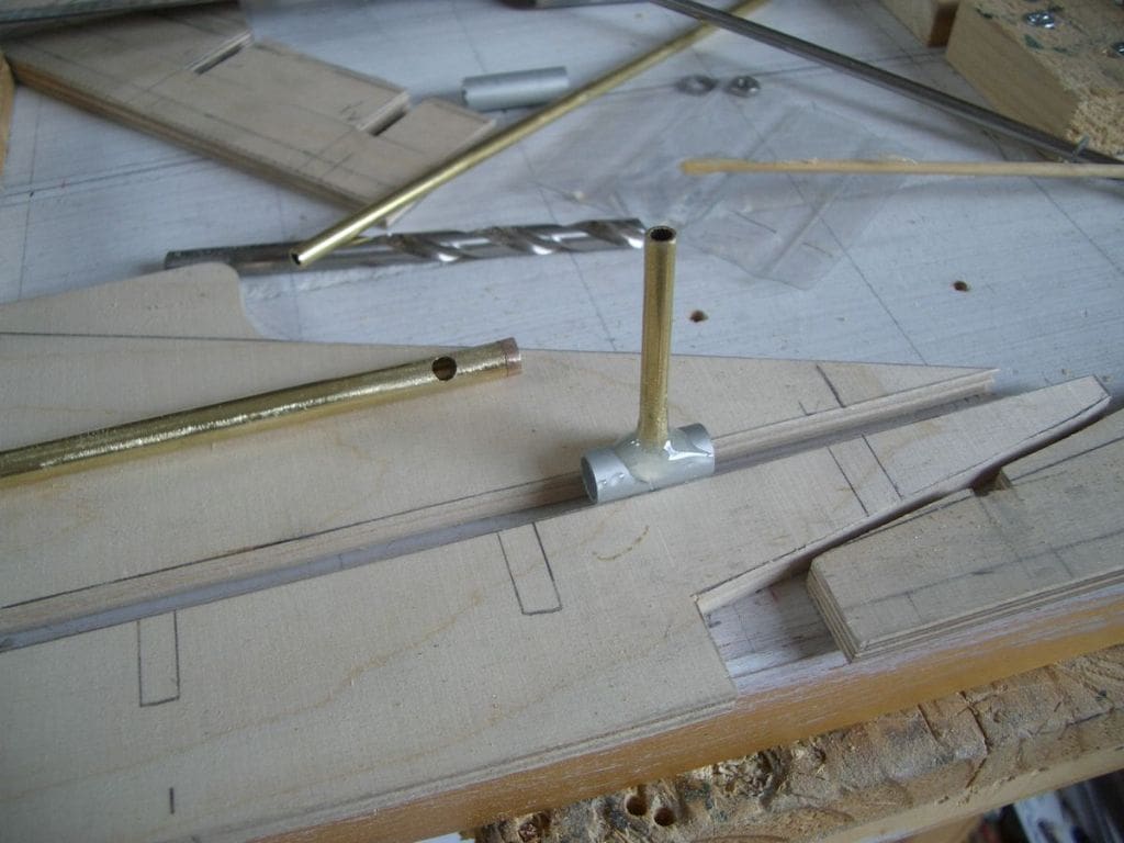
Following advice, a MFA 550 motor with a 2.5:1 reduction gear was installed, running off 12 volts. The oil filler in the propshaft, was epoxied to a sleeve which gave a substantial joint and saved me some soldering, Photo 1. Radio control is by a 2.4GHz transmitter and receiver from Giant Cod RC and these have proved to be excellent despite the very low price which had concerned me at first.
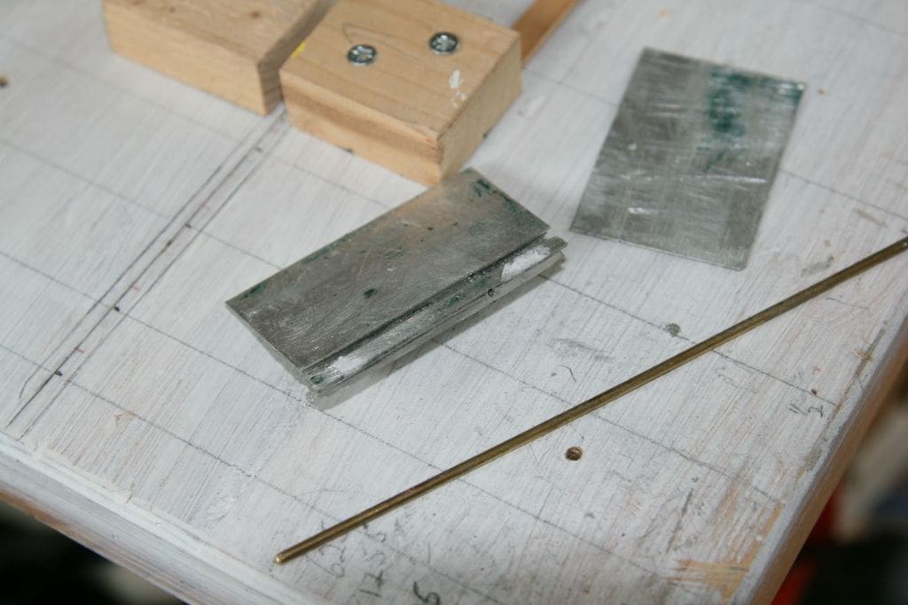
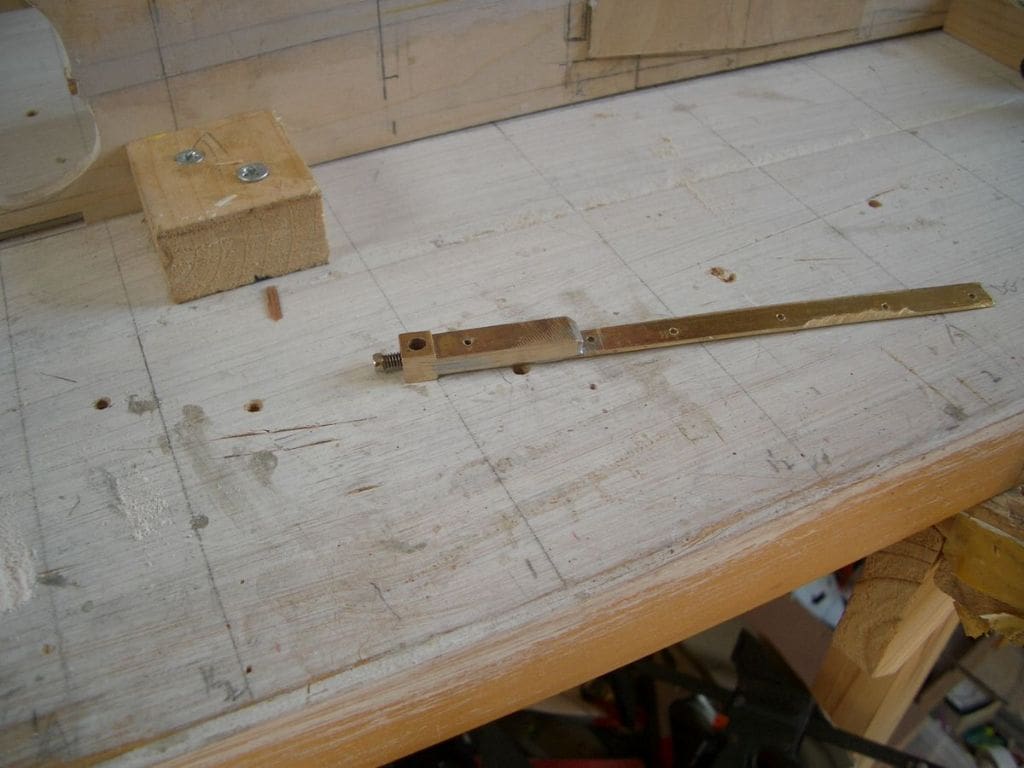
The rudder was constructed with seven layers of aluminium glued and pinned to a brass rod, Photo 2. I probably went overboard on this but I wanted a good substantial job. The rudder bottom support skeg was produced by using the earth pin from a 13 amp plug, soldered to a brass strip, Photo 3.
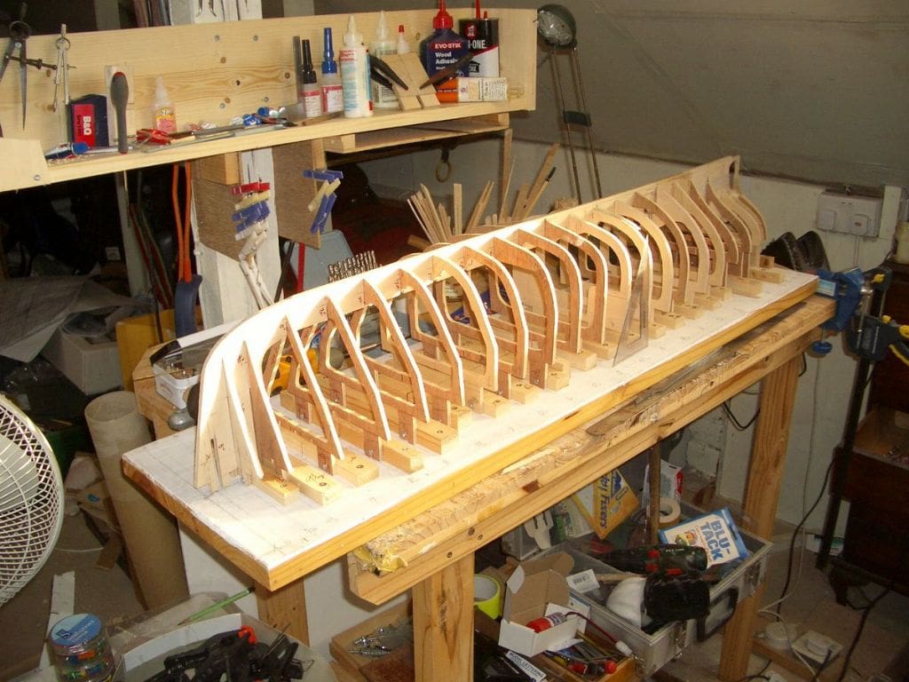
Basic hull
Cutting out the bulkheads was fairly straightforward but required careful marking out near the keel as the lines were very close together. The hull was built upside down on a building board, again following advice on the website forums, Photo 4. It was obvious that the sharply curved stern would be too difficult to plank on bulkheads so solid balsa blocks were glued in place in the time honoured way. This worked well and certainly made it easier to plank as the compound curves which would have required much plank bending and twisting were thus avoided.
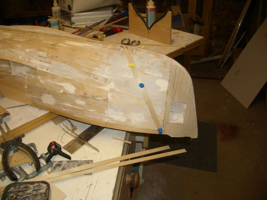
The first layer of planking was not too difficult and was glued and pinned to the frames, but the second layer, which was to be fixed diagonally to the first, was much more difficult to pin and glue and eventually I found it best to just use superglue on its own, Photo 5.
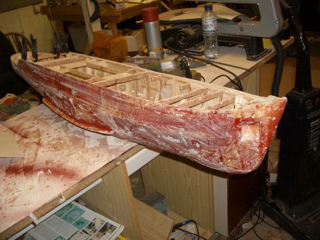
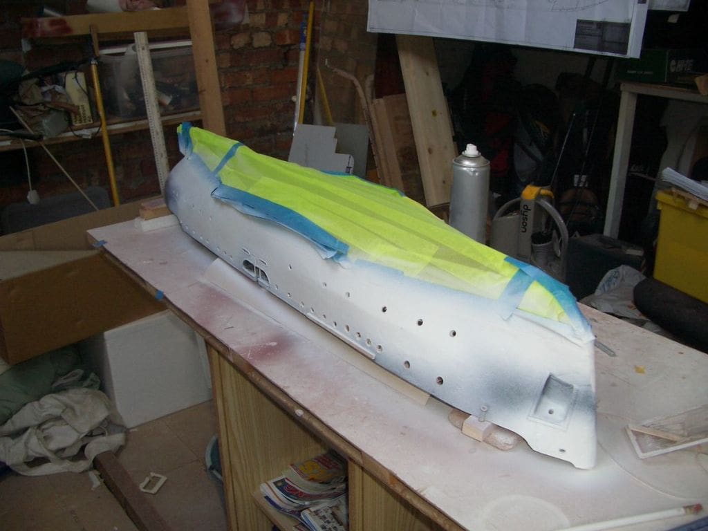
Fibreglass mat and resin was then applied over the whole hull. A lot of rubbing down was required, but the end result was very satisfactory, Photo 6. (Editor’s note: Always be careful when rubbing down fibreglass, Wear an appropriate mask and protective clothing of some sort, even if just an old jacket. Fibreglass dust can make you itch and what it could do to your lungs, even some decades later, doesn’t bear thinking about.)
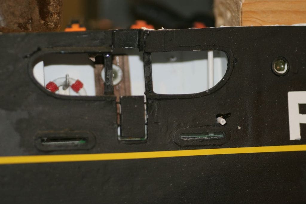
Pilot’s Entry Port
This was tricky as it needed to be constructed prior to fitting the main deck and of course also had to be watertight. This section actually has a fair bit of detail but some simplifications were made on the model, otherwise it would have just looked too cluttered. There were also a few differences between the builder’s plans and the actual ship on display at Liverpool. This is not unusual, as owners often ask for changes during construction, or indeed after the vessel has been completed and entered service. I opted to make the model as practicably authentic to the actual ship as photographed rather than the builder’s plans, Photo 7.
Portholes
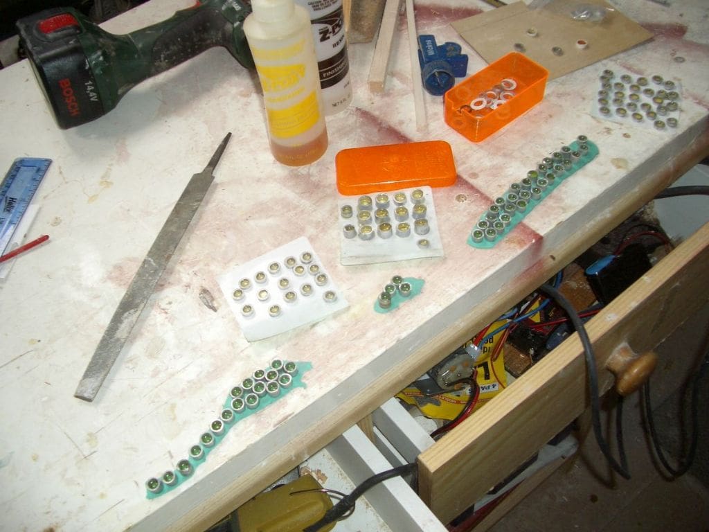
There are rather a lot of these, 62 in the hull alone and the thought of drilling all those holes in the hull filled me with dread! Alignment is critical, since one out of line will stick out like a sore thumb. The portholes themselves were made by cutting short lengths of aluminium tube which were then stuck onto Blu-Tack. Each was then filled three quarters full with clear resin. This gave a very good result as the resin tended to set slightly concave which looks quite realistic, Photo 8. These were later installed into the pre-drilled holes in the hull.
Painting and deck
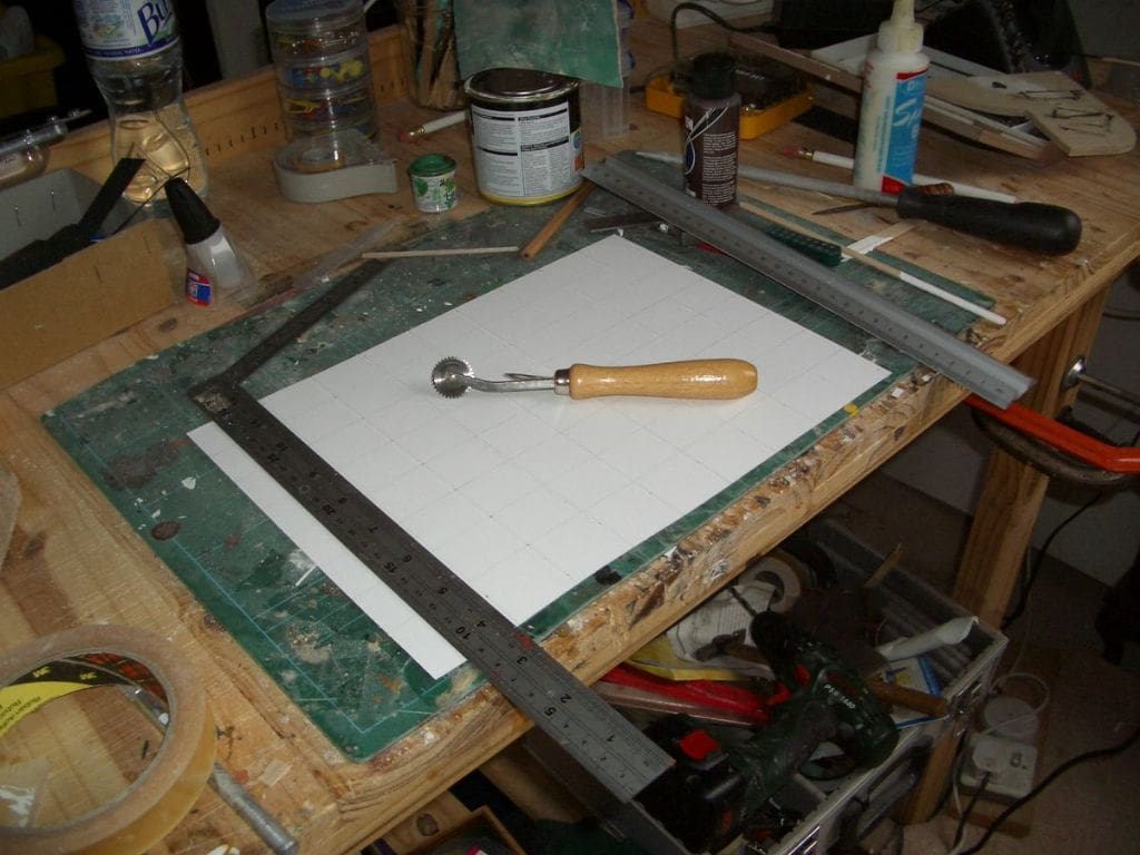
Next up was to paint the hull and the plywood decking. The forward deck, which is actually steel and not planked, was covered in paper sections marked out with rivets using one of my wife’s sewing implements, namely a tracing wheel, Photo 9. Very handy was this tool and if it went wrong it was no problem to have a go with another piece of paper.
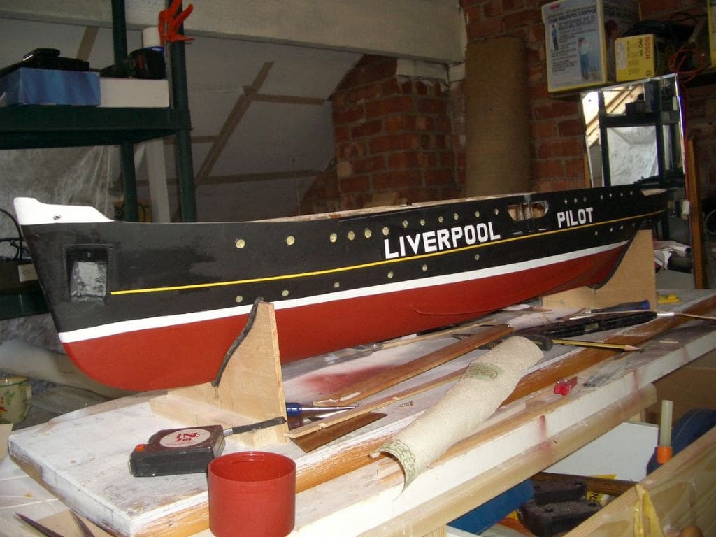
I used the usual Halford’s acrylic car sprays for the hull. The area where the words ‘LIVERPOOL PILOT’ were to appear was sprayed white, Photo 10, followed by the application of masking tape lettering, cut out with care on a self-healing cutting board,. This proved to be a daunting task but I did not want to purchase lettering although this might have given a more professional finish. After over-spraying with several coats of black, the masking tape was removed. The result seemed to be a minor miracle, Photo 11.
Ply, 1/16 inch thick, was used for the deck which is quite thin, but as the ‘wooden’ part of it was to be individually planked, the added thickness of these planks would make it all more rigid, as proved to be the case.
The edges of the planks, which were cut 1/8 inch wide, were marked with Indian ink to represent the caulking. This produced a good, but rather heavy look. However, once sanded down, the effect improved, Photo 12.
Superstructure
The superstructure is a mix of plywood and styrene card but also a fair amount of paper.
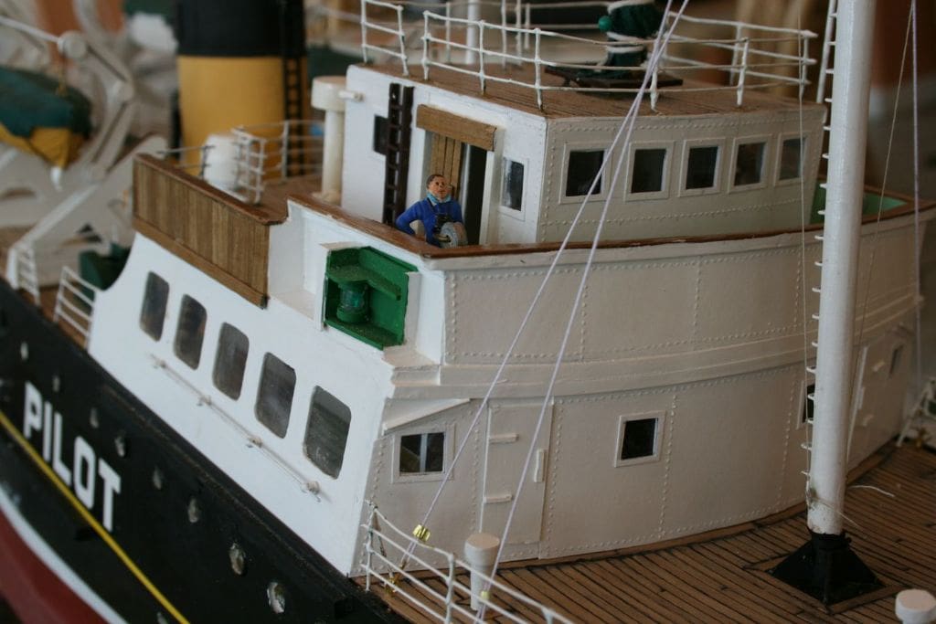
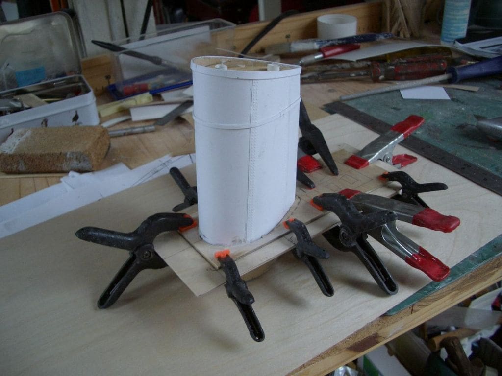
Most of the superstructure was covered with paper with simulated rivets as for the foredeck. Photo 13 is of the completed superstructure and the rivets can be clearly seen on the front face of it. Paper is very useful for providing detail after soaking with glue. This method was used for constructing the bands around the funnel after covering the funnel with paper and simulated rivets, Photo 14. Once painted, glued paper is quite resilient.
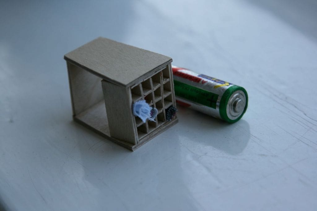
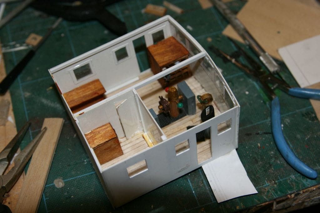
Photo 15 is a of a flag locker and Photo 16 is of the internal bridge detail. Being able to photograph the original helps no end with constructing a model. I wanted to provide lighting within the bridge, but didn’t want to have to connect wires every time the superstructure was removed. To overcome this problem, brass sheet was glued (epoxy) to the inside of the superstructure where it overlapped the coamings. The lighting wires were soldered to these pieces of brass. A matching connector plate was fitted to the coaming (both port and starboard) so that contact was made every time the superstructure was fitted on to the hull, Photo 17.
Lifeboats and davits
These required quite a lot of work and a mix of ply and styrene card was used for the davits, the lifeboats being carved from balsa. The lifeboats were stowed covered as this not only made life easier for me, but I have also never seen them uncovered on the actual vessel.
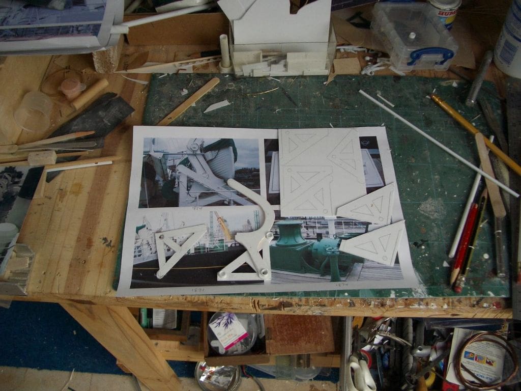
The davits were a very time consuming job and were based on photographs. There were no precise measurements for them, even on the plan, so there was a certain amount of guesswork involved together with reference to the pictures, Photo 18. Each lifeboat and its davits are fastened to a separate piece of planked ply, which is then screwed to the deck, but is also removable. The idea being that first they were easy to make as individual units, and second if damaged the whole assembly could be easily removed for repair.
Deck machinery
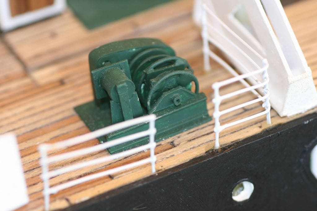
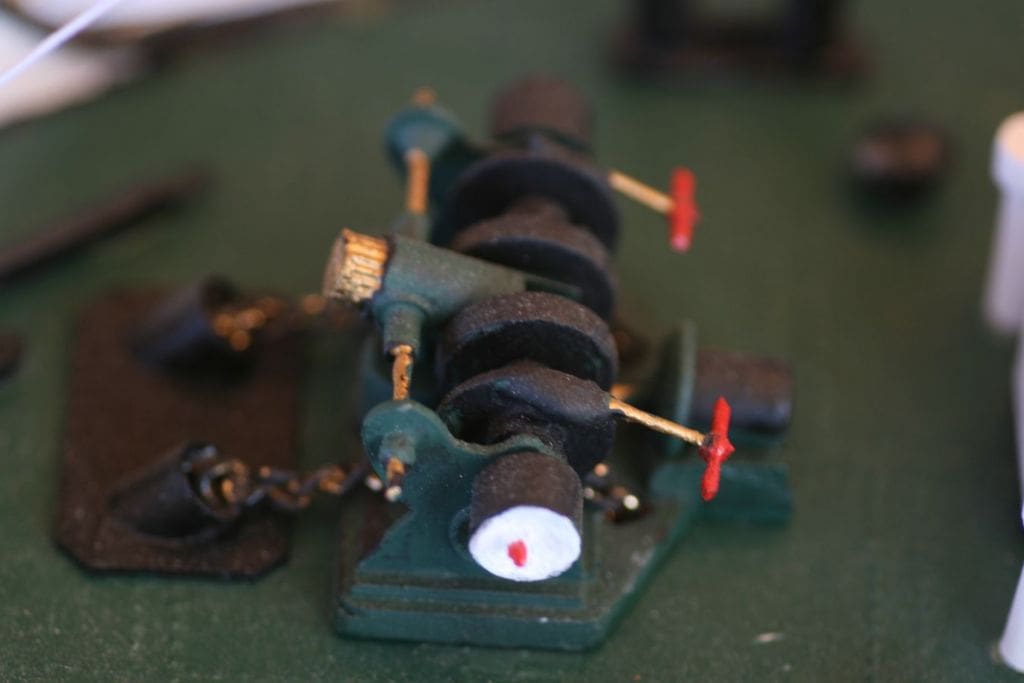
The winches and lifeboat lifting machinery were a challenge, Photo 19. Since this was a scratch built project, using commercially made items that ‘would do’ was not an option. These davit winches were constructed from bits and pieces. If broken down into small sections, the task became quite easy.
However, the forward anchor winch posed a bit of a problem, as that on the vessel always seemed to be covered, so back to intelligent guesswork and a bit of modeller’s licence. Once again, all sorts of bits and pieces including golf tees and tops of toothpaste tubes were utilised, Photo 20. The serrated tops from toothpaste tubes, when filled with Milliput, can be sliced into gear wheels. Copper wire, stripped from electrical cable is also very useful and usually ready to hand.
Handrails and radar mast
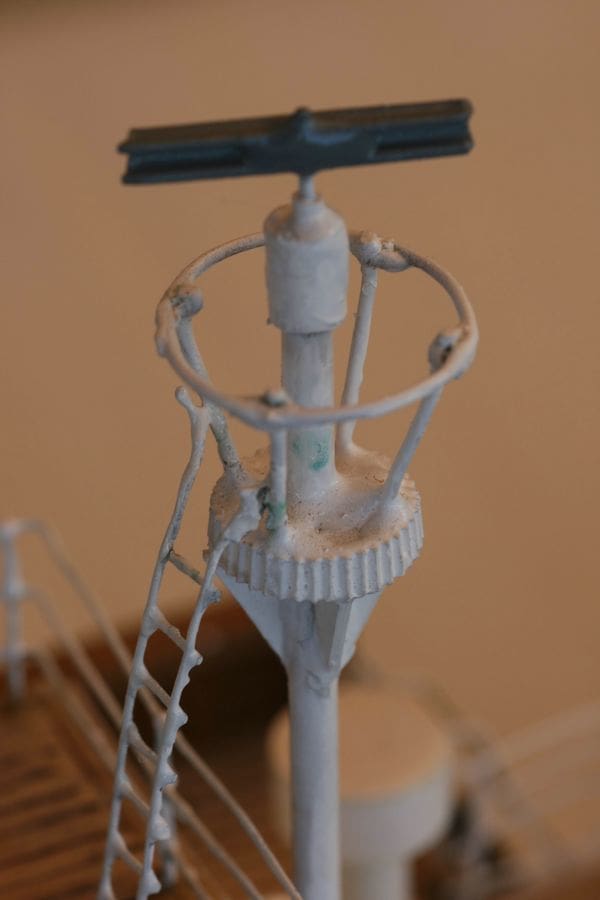
Fine soldering was going to be new to me, so I was faced with a steep learning curve. First I tackled the radar mast, Photo 21. This required two wire circles and the first attempt was abysmal and had to be discarded, but the second attempt was better. The standard of soldering seen at model boat shows or in this magazine can be quite daunting, but don’t be put off as it is very satisfying, even if the result like mine, is not that good.
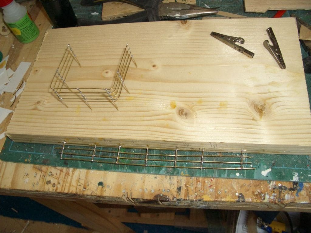
For stanchions I used those supplied by James Lane who advertises in this magazine. He also supplies the railing wire which has to be stretched prior to use. First, I endeavoured to fix the stanchions in the deck and then thread the wire through. This didn’t work too well, so I then tried a simple jig to hold the stanchions precisely and then threaded the wire through followed by soldering, Photo 22. This produced lengths of railing which were bent to shape before marking and drilling the deck and secured with small amounts of carefully applied glue. The secondary benefit of this was that the railings could be painted ‘off model’.
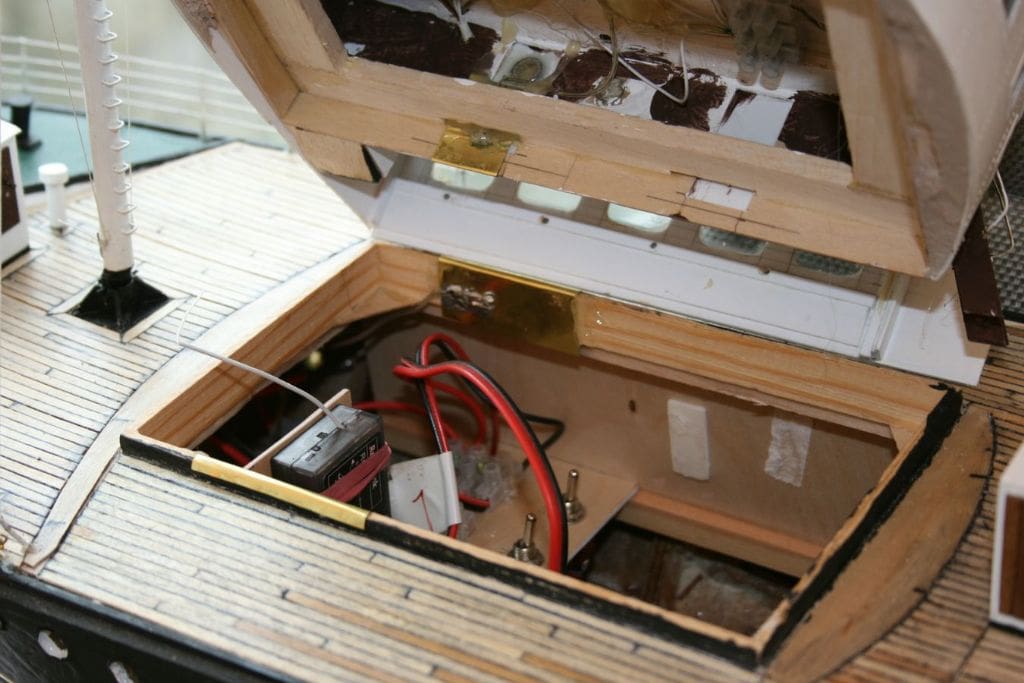
Hull access
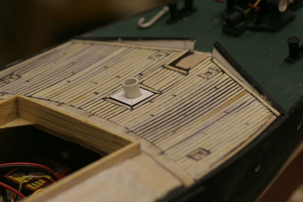
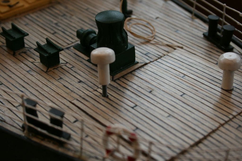
Where access to the hull, other than the bridge area, was required, individual small areas of deck had to be removable. A tight unobtrusive fit was required together with ease of removal, but also a secure location. This was resolved by making the ventilator uprights from aluminium tubing with a bolt epoxied inside and the matching nut epoxied under the deck support, Photo 23. This ensured secure location, but also ease of removal. Okay, a bit of modeller’s licence as some of the vents have been moved, but no one notices except me. On Edmund Gardner. there are so many of these vents and machinery on deck that this could be safely ‘got away with’. As it so happens, I have never seen such a cluttered deck as that on Edmund Gardner.
Masts and rigging and figures
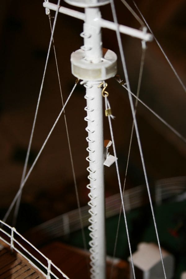
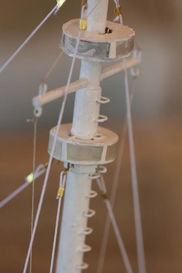
Aluminium tube was the first choice for the masts, but as they both have climbing rungs, wood proved more suitable. The rungs were quite easy to form by bending short lengths of wire, but a lot of patience marking correctly and then drilling the masts for them prior to fixing was required, Photo 24.
The two light clusters on the foremast had me puzzled for a while, as they appear to wrap completely around the mast. A plastic top off a bottle of water which while difficult to cut, produced a reasonable result for each one, Photo 25. The rigging is white elastic. Purists might moan, but it all remains taut and also has some ‘give’ in the event of a stray hand coming into contact with the rigging.
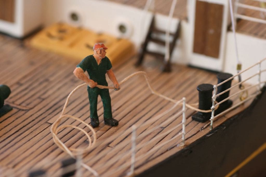
The figures were purchased, as a model without crew or passengers is a pet hate of mine, Photo 26.
Edmund Gardner in the Graving Dock
The area around the Maritime Museum in Liverpool has been undergoing redevelopment for some time now and when I visited, it was not actually open to the public. However, the staff on the construction site were kind enough to accompany me to the ship when I explained why I needed to take photographs. So, without their help this model could not have been constructed. I have always been rather worried at having a go at a scratch built model, those at shows being of such a high standard. It is easy to feel inferior to these master model builders, but I would urge anyone to have a go. Believe me, if I can do it then so can you, it just requires patience and breaking, where possible, the task in hand down to small units of construction. I would also like to thank those who gave me much good advice on the Model Boats website forum as well as others.

