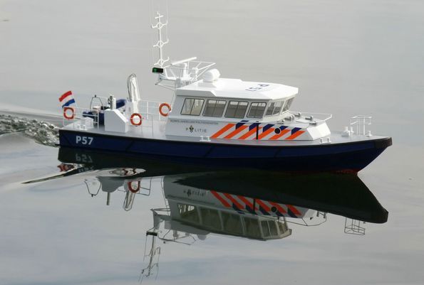
Damen Stan Dutch Police Launch
JOHN ELLIOTT reviews the Deans Marine R.A.M.B. model
Enjoy more Model Boats Magazine reading in the monthly magazine.
Click here to subscribe & save.
Type of kit
This is a new venture for Deans Marine. At one end of the modelling kit spectrum we have the traditional type which involves a reasonable amount of skill. At the other end is the A.R.T.R. (Almost Ready To Run) which usually only requires the installation of batteries and radio equipment before you can sail. This kit has been classed as R.A.M.B (Rapid Assembly Model Boat) and falls somewhere between the two, but closer to the A.R.T.R. Although this was a limited edition kit and the first batch run closed in late 2009, I understand that there were plenty in stock and for sale early in 2010.
About the kit
Photo 1 is of what is in the large box. The main item is a moulded high impact styrene hull with the propshafts, rudders and linkages already installed. It is pre-painted red below the waterline, blue above and the deck is grey, all in a satin/semi-gloss finish with the rubbing strakes picked out in black. The cabin has been pre-assembled, painted white and all the glazing and window frames are pre-fitted. Brass tube and rod have been used for the mast and railings, which have been bent to shape, soldered and painted, The separate top mast even comes in its own protective box. Other items include a Hiab crane, a Sea Raider inflatable, life raft, life belts, other fittings, stainless steel propshafts and brass propellers. Also enclosed is a sheet of vinyl decals (Stickers are provided for either P47 or P57), motor mounts and battery trays along with an assembly guide that details the construction sequence, adhesives required and the parts to motorise it.
What extras will be required?
To complete the kit to the on the water stage you will need to source two motors, two couplings, one or two speed controllers, batteries, glues and a minimum two channel radio with one servo for steering. The recommended items are specified in the manual and most have been used in this review. It would be worth considering purchasing a constructional CD from Deans Marine (send £2 plus a sealed blank disc) as it will then contain over 100 photos taken during construction of the prototype.
Fitting the cabin
After unpacking and checking the components, assembly can begin. I started with the cabin as per the instructions. The hull has a moulded coaming that the cabin fits over and as the deck is curved the cabin will have to be trimmed to fit at the front and back. This is done by raising the cabin on its four corners to the level of the lead of a pencil held flat on the deck. The soft pencil is moved across the deck to mark the area to be trimmed, Photo 2. Now, some words of caution. Be very careful when trimming the cabin as the front three panels are quite small and on my example a lot of this had to be removed. Although I thought I was taking care, one of the panels became detached and had to be glued back in place. In fact I filled the space behind them with Isopon P38 filler to give them some support, so I would suggest this area is reinforced before you start removing the surplus. Also be very careful how you hold the cabin as too much hand pressure could break a joint. The cabin is actually supplied built up from sheet styrene as we would when scratch building. The best method to remove the surplus would be by using a small rotary sanding drum. As with all this type of work, remove small pieces at a time and keep checking the fit. This is probably the single most difficult assembly part of the kit to perform.
Running gear
The next step was to install the propshafts (into their tubes), the motors and rudder servo. The motors (not supplied) will requiring wiring and suppression if not already so equipped. The propshafts had any burrs gently removed from their threads with a fine file, were smeared with a little oil and then slid into place. The washers, nuts and props were placed on the outer ends and then the couplings were temporarily slid over the other ends to gauge the positions for the motors in the hull. It is always best to include a little slack in the drive train so that everything turns freely.
There are quite a number of couplings on the market. Some are intended for small low powered models and others for boats like large tugs that require something more substantial. Deans Marine recommends the Nycrome extra long type for this kit, Photo 3. The range comes in various sizes of ends and also with different overall lengths. They were originally designed for warships and are really very compact offering a neat installation. They can be supplied with screws, or as I prefer, grub screws that are fastened with an Allen key. There are a number of different types available from Deans Marine and it is well worth a look at their website for the complete range.
The propellers and shafts were then removed from the model and the couplings permanently fixed to the motor shafts and propshafts. Why? Well as you can see from the pictures the couplings and their retaining screws are under the deck with no vertical access for an Allen key so it is easier to do it externally from the model. The shafts, couplings and motors were then slid back into position and the propellers refitted, but of course we are now left with the motors hanging loose unsupported in the hull – not good model building!
All is not lost though as two vac-formed motor mounts are supplied with the kit. These were placed under the motors and moved around and adjusted until the shafts, couplings and motors were in alignment. This is actually easier than it would seem and their positions were marked on the hull bottom and then they were temporarily removed prior to final gluing in place.
Before that though, the rudder servo mounting had to be prepared. Printed styrene card is provided to make a shelf for the servo to be fitted with double sided tape. I am sure this would be okay, but I much prefer the rudder servo to be securely screwed in place, so I made up my own mounting using the material supplied (good recycling here!) of which there is plenty. The servo mounting was glued in the indicated position, ensuring the starboard motor mount would not be obstructed, Photos 4 and 5.
I now returned to the motor mounts and cut holes for the cable ties which will retain the motors. These were threaded through the holes and the mounts were then glued into the hull in the previously marked positions. Remember to scrape and abrade the glue contact areas and it is easier to put the cable ties in before gluing as it could be difficult to thread them when in-situ. Once the glue had set I added double sided sticky pads onto the mounts as in Photo 6, positioned the motors and tensioned the cable ties. Photo 7 is of the motors properly secured and also the rudder linkage arrangements. An adjustable connector gives some flexibility but you could just put a Z bend into the end of the rod if you so wish. A tray was cut from the styrene card supplied to mount the radio receiver and the speed controller, Photo 8. A wiring layout is included in the instructions but it really is very simple to connect everything together. I always use plugs and sockets on the connections between the motors and esc as it is easier to test the system if you have electrical problems in the future. I installed just a single Mtroniks 15 amp electronic speed controller which works well. I have not installed any mixing device or individual motor control, but there is bags of room in the hull should you wish to go down that route. Remember the propellers are left and right handed, so you must reverse the wiring to one motor so they turn in opposite directions for forward motion.
Underneath the hull at the stern, ‘P’ brackets are glued between the shaft and hull to support the extremities of the propshafts and also help prevent vibration. Some very minor adjustments with a file were necessary to ensure they fitted snuggly.
Mast and cabin
Supports for the deck railings, which are just strips of styrene, were glued under the deck as instructed but my attention now returned to the cabin and fitting of the mast.
Five support blocks are cut from the plastic sheet. One is glued to the inside of the cabin rear panel and the other four to make a spacer between the cabin and the mast assembly. When dry the holes are re-drilled to match each other and the two components bolted together. Unfortunately the bolts supplied in my kit were not long enough so had to be replaced. I also found the mast did not fit flush to the deck when the bolts were tightened, due to the fact that the rear cabin panel slopes towards the bows. You could trim the bottom of the mast, but my solution was to add a further small strip of plastic to the top of the block to increase the angle, Photos 9 and 10. The rest of the mast was then assembled following the instructions.
Holes in the mast for mounting the pivoting A Frame will need to be drilled. The whole assembly is of brass so care is needed to ensure the drill tip does not slip. Start with a small drill and open up the holes is as good away as any. Rather than use pieces of wire to hold the A Frame in place, I used small 2mm nuts and bolts which look better and enable disassembly, Photo 11.
Some method of fixing the cabin to the hull is necessary so that it is not lost at sea and there are suggested ways and means for this in the instructions, one of which is to use an elastic band secured to the hull and a hook inside the cabin, but my method was to bolt the cabin to the deck. A long bolt that was part of a spring loaded cavity wall fixing from my DIY box proved to be ideal. A suitable hole was drilled in the box section of the mast to take the bolt, Photo 12. I cut a small piece of styrene tube that was blocked at one end and fitted this over the bolt head with the internal void filled with epoxy resin, Photo 13. The purpose of this being to disguise the bolt head. A cap from a toothpaste tube or similar might also be suitable.
The next step was to mark its position on the deck and drill another hole, Photo 14. The nut has to be secured under the deck and some hidden reinforcing will need to be added. The easiest way of securing the nut is to place it on masking tape, sticky side upwards, then apply a small amount of superglue to the upper surface of the nut and move it into position under the hole using the masking tape to facilitate the task, Photo 15. Try not to glue your fingers to the tape or get glue on the threads of the nut. Once secure, the tape was removed and using a mirror some epoxy glue was added around the nut underneath the deck to strengthen its fixing. Now, the disguised bolt can be dropped through the mast base and secured to the nut. The bolt head, being disguised, does not look out of place within the mast assembly.
Power supply
I wanted to use a 7.2 volt battery pack because I use them in some of my other boats, so the two supplied battery trays supplied were not used on this occasion. A spare tray from my bits box was suitable, but one can easily be made if you wish to match your battery pack(s). This was placed in the rear section of the hull between the rudders and secured to the bottom of the hull using double sided tape, Photo 16.
Rear hatch
Whilst installing the battery box I had to think how best to secure the rear hatch and a simple solution was to apply foam tape around the edges. This then grips the lip making a reasonably watertight joint, Photo 17.
Remaining fittings
With all the major parts taken care of, all that is left are the fittings. Looking at the pictures on the box and in the illustrated instructions, the relative positions of them all is easy to determine and the bollard locations are actually already marked on the deck. However, the gap between the stern and rear hatch is only just sufficient for the Hiab and life raft and also the rear hatch arrangement with the inflatable boat could make for some problems when removing it to recharge the battery. I have used some modeller’s licence here and slightly rearranged these items as can be seen in the pictures.
The first task was to put a small access hatch/cover for the on/off switch from the speed controller and also the ends of the extended oiler tubes from the propshafts. This is just in front of the main removable rear hatch. Photo 18 is of the coaming for that hatch in place. The hatch itself was used as a template for the coaming which was made from scrap styrene. It will be necessary to carefully remove the paint from the deck area where the coaming is to be fixed.
Bollards were next. Where possible I would suggest pinning as well as gluing all the fittings in their correct positions and matching holes in the deck will be required where they are to go. If the hole is countersunk this also goes some way to preventing glue oozing out from under the fitting, Photo 19.
The deck is pre-drilled to accommodate the railings and all that has to be done is to drill through the reinforcing strips previously fixed under the deck and glue them in position. The main exhaust block has to be profiled to sit vertically on the deck so rather than just glueing it in position another coaming similar to the small hatch was made. This could be used for more switches should the model builder later decide to install working lights or similar, Photo 20.
The Sea Raider inflatable was easily assembled and improved by adding some grab ropes around the outside, Photo 21. This was then fitted to the rear hatch from port to starboard rather than fore and aft as in the instructions. This ensures both can easily be removed for hull access. The hydraulic tubing on the crane was represented by some fine painted wire. Photo 22 is a general view of the slightly revised stern deck area. Last, but not least, was the addition of the self-adhesive decorative decals and there no problems with these.
On the Water
Prior to going to the lake there was the inevitable bath test. Would it float? Well, yes it did and approx. 1kg of ballast was required amidships and 0.5kg at the stern to bring the model to the painted waterline, or so it appeared, but more on this later. Anyway off to the Brentwood MY&PBC lake with your Editor in tow for a test session.
The instructions suggest two scenarios, one for optimum running time and one for speed. The first uses the propellers supplied but with geared motors and the second uses smaller propellers but ungeared. Now as it was not practical to change the direct drive motors for geared units, the test was done with different size propellers.
After the usual checks and with the larger propellers on direct drive motors, off she went and somewhat disappointingly was smooth running, but not very quick. After a few minutes sailing it was brought back to the bank and checked. The battery was hot and was already getting close to ‘dumping’. On the other hand, the motors rated for 6 to 12v were not particularly warm at all.
The propellers were changed for smaller versions and the model re-launched. This time there was an improved speed performance but still not as much as was expected. It seemed to be biting into the water instead of the bows lifting. So we removed the amidships ballast and tried again. There was a further noticeable performance improvement, but the stern was now digging deeper into the water. So, out of the water again and the stern ballast was removed. It now sat very slightly above the waterline with a bit more red bottom showing at the bows, but the performance improvement was very noticeable from the first run and now judged to be satisfactory.
Conclusion
For best performance no ballast is necessary other than to correct a list (if any) and the smaller propellers on direct drive from the Kestrel motors are worth the additional cost. As the motors were only running on 7.2v it follows that an 8.4v or 9.6v battery should give more speed and longer running time but that is a matter of choice. The model was a pleasure to build and looks impressive on the water. This type of kit may well suit those that don’t have workshop facilities or sufficient free time but still want to have some modelling input to their models. Deans Marine have always prided themselves on customer service and I cannot fault them with this model which fills a useful niche in the market.
Model Specification
Price: £325 (January 2010)
Scale: 1/20
Length: 950mm
Beam: 250mm
Recommended extras required:
Two of Kestrel motors (or Navy geared from Deans Marine)
Two of Nycrome EX/L Couplings 3.19mm/4mm with plain ends
One (or two) electronic speed controllers to match
NiMh power pack (I used a 7.2v 3000mAh sub-C pack)
Brass propellers for fast launches, No. 162 x two from Deans Marine
Minimum of two channel r/c with a standard rudder servo