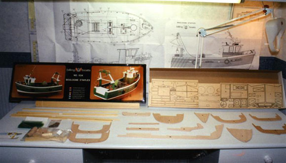
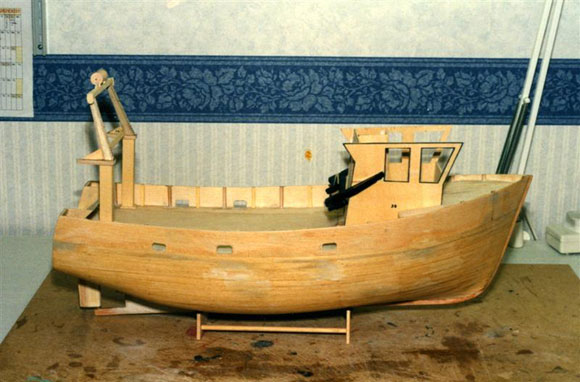
I was attracted to this model some years ago before I took up the hobby. Whilst visiting one of my friends, I noticed he had acquired this kit, minus some parts and the fittings. This rekindled my interest in the model as it was ‘plank-on-frame’, a method of construction I had not tried previously. After looking through the advertisements in Model Boats I found it was still readily available from a number of shops including Westbourne Model Centre at around £109. What’s in the box?The complete kit consists of two packages, one containing the fittings and the other the wooden parts. The first thing I did was to check all the parts were correct and not damaged, Photo 1. This was made quite simple as a parts list is included. I did find one broken piece, which was replaced promptly by the importer. The next stage was to study the instructions and plans thoroughly. These consist of diagrams with very little written explanation. Two full size drawings are also included. Although this is satisfactory for someone who has some knowledge of model construction, I would think a beginner might find them lacking at times. Enjoy more Model Boats Magazine reading. Click here to subscribe & save. Basic constructionNow down to business! The first step was to cut out all the parts using a fret saw. Fortunately I was able to borrow an electric Vibrosaw, which made the task much quicker and more accurate. One point I will stress when cutting out the components, is to cut outside of the lines, to allow for any adjustments to be made when fitting parts together later. The first addition I made to the kit was to solder an oiling tube to the propeller shaft. This was done using a small piece of brass tube available from most model shops. I drilled a hole slightly larger than the oil tube, 10mm from the end of the propeller shaft tube. I bent the oil tube so that it would clear the battery terminals when installed. It was then forced into the hole and soldered using a general purpose soldering iron. The hull base was made as per the diagram and the keel constructed with propshaft fitted and the oil tube at the correct angle, Photo 2. The next stage was to glue together the ribs, Photo 3. I did another small modification here, which was to cut out the centre of ribs 6, 7 and 8. I did this to allow access to the inside of the planking, for sealing with epoxy resin or fibreglass later on in the build process. Care is needed to ensure the ribs are glued at the correct distance apart and are square in all planes. When this has dried, parts 56 can be glued to the top of the ribs. I used the deck, parts 15, to check that the distance between ribs was correct. I also checked the level of the ribs to ensure the hull would be straight. I know it takes a little time to keep checking, but it is worth it in the long run and will save time trying to correct mistakes later. The diagram in the instructions shows the next stage for fixing the deck. I decided not to do this, to allow me greater access to the planking for sealing later. I temporarily fixed the deck to the ribs with pegs and clamps. Parts 20, the deck edge bulwarks, were next soaked in hot water to make them pliable and then pinned and clamped to the ribs. I left these overnight to dry and then removed the clamps and pins. These parts had now taken up the shape and would now make gluing easier, as they will now not try to ‘spring away’. Before you glue them, the ribs will need a little shaping to match the curve of the hull, so that the planks sit squarely, Photo 4. Next comes the planking. I found it best to allow yourself several days to do this, completing about three to four planks each side, per evening. I soaked the planks that would be used that evening, for about an hour in a container of hot water. This was sufficient to make them pliable. As before, I pinned them into position and allowed them to dry before gluing. I did not pin each plank permanently with the pins provided but used modelling pins to hold them whilst the glue set. The reasoning behind this, is that the pins can work their way to the surface at a later date, splitting and spoiling the finish to the hull. The first eight planks each side did not need any trimming to allow them to sit flush to each other and the ribs. The next eight needed trimming, Photo 5. I did this by pinning as much of the plank as possible to the ribs and then marked with a soft pencil, the area to be removed. A small David’s Plane is very useful to do this. The next plank was impossible to fit to the entire length of the hull. I fixed it as before, but when trimmed it only covered three ribs. This situation continued for the next couple of planks until the curvature flattened out. I am told these short planks are called ‘stealers’. The planking continued until the complete hull was covered, Photo 6. It is worth remembering that it is best to trim a bit off each plank, rather than ending up trying to fit a thin plank at the end. As I said before, this was my first attempt at plank- on-frame construction. I have learnt from this attempt that it is well worth taking your time when trimming the planks and far better to trim a little from each plank. You may find that this will overcome the need for stealers in some cases and reduce the amount of finishing required. Once the completed hull had dried for a day, I sanded it down with fine glass paper, wrapped around a sanding block. This will help to avoid making low spots as the material is relatively soft. Any gaps that remained were filled with P38 car body filler available from motor accessory shops. This was then rubbed down as before, until smooth. The outside was then coated with several coats of sanding sealer, rubbed down lightly between coats. The finish achieved was excellent. Another method of finishing the hull is to cover it in tissue as used by aero modellers and then painting it with dope. The tissue is cut in suitable pieces to avoid excessive creasing, each piece being butted or slightly overlapped. When sanded and coated with several more coats of dope, the joints are invisible and a good finish is obtained, giving the hull extra strength. To give my hull additional strength I coated the inside with strips of fibreglass matting and resin, again available from motor accessory shops. This was the reason for not gluing the deck in position previously. The resin was mixed and poured inside the hull, which was rotated up and down, so that all parts were covered. The mat was pressed into the resin with a brush and then coated with more resin. It is best to only mix small quantities as there is only a limited time before the resin starts to harden. When this has been completed and it has dried, you will end up with a very strong structure that is totally sealed and waterproof. The next item to be made is the stand. The one provided is quite adequate for use during construction, but I feel something more substantial is required for use at the pondside.
|
|
The rudderThe rudder was the next item on the agenda. First drill the keel to accept part F317. The tube was glued into the hull using 5min Araldite. The centre wooden parts were glued to one outside piece but not to the shaft. When set, the other outside piece can be held in place whilst the rudder is shaped. The shaft is now pushed through the tube from the top, through the rudder and into the keel, part F317. If you are happy with this set up, the rudder can be sandwiched around the shaft using araldite and left to set. If you had glued the shaft to the rudder as shown in the instructions you would have great difficulty in getting the components into position. The tiller can now be fixed with the two nuts. I was not convinced that this would be substantial or long enough to give sufficient travel when connected to a servo. So I replaced it with one I made from a piece of brass strip, soldering it as well, to ensure that it did not move. The deckNext came the deck. I cut off the pieces of deck that fit between ribs 6 and 7 to allow access to this area when the cabin is removed. This can be remade later so that the cabin is supported, but made removable. The deck needed a little trimming, to give a close fit to the bulwarks, before gluing into position. The joints can then be filled and sanded to give a level surface. I trimmed the stern ends of the deck part 15, where part 22 fits, since when parts 18 to 21 are fitted, access is difficult. The angle is made for parts 18 to 21 by using a block of wood and some fine glass paper. You must make sure parts 18 and 19 are the correct way around, Photo 7. The position of the freeing ports in the bulwarks were checked and marked out. Small holes were initially drilled in them to allow a fretsaw blade to be inserted. I held this at both ends with a thin piece of card and carefully cut them out, finishing off with small files. Deck part 22 was fitted into deck part 15, with allowances for the curvature. The framework for this is made next and if you line up all the parts with the deck, the correct curvature can be obtained. When completed, the frame did not have sufficient strength to overcome the pull of the deck part 22, so did not give it a tight fit. In the end I cut out the original supports in the hull, parts 56, reinforced the frames with thicker timber and built up the deck with thin layers of ply. This was sanded to suit the curvature of the deck and provided a much sturdier structure, which hopefully would stand a better chance of being watertight and not being washed away. Rather than just gluing the hatch to the deck I cut a suitable hole in the deck, made up a coaming and then fitted the hatch to it. I now had access to put some switches in later. The gantryNext came the gantry, Photo 8. This is quite easy to assemble, but care is needed to ensure both sides match one another. This can be done by making one and then cutting templates from it in card. These are then turned over to give a mirror image, to be used to construct its partner. I fixed bolts into the bottom of the gantry for more strength when fitted to the deck. It will also allow it to be removed easily for repair, should it sustain damage in the future. The wire components are bent to shape, using the full scale plan as a template and soldered together. The winch is again a simple structure. By using a thin bolt to clamp part 34 (four parts) together. They can be held in the chuck of an electric drill and if this is rotated slowly, the parts can be made circular and the same size, with the aid of a block of wood and glasspaper. The same process can then be used to bevel the edge of the pulleys.
|
|
The cabinThe cabin was the next item to construct, Photo 9. I clamped the two sides together, trimming them to the same size. I placed these on the deck in the correct position and took the measurements for the front and back components. The angle of part 42 was then checked against part 38 and trimmed. It is important to ensure everything fits and is at the correct angle – so ‘patience’ is the key word. At each stage I made sure that the cabin would fit between the side decks before final gluing. I decided to add a floor of thin ply to the cabin, to increase its strength. A small piece of scrap wood was added to the front just below the deck. This stopped the cabin being lifted out of its final position vertically. When the deck is in position the cabin will then be held in place securely. I nearly lost my sanity trying to glue the vent louvres, parts 61, to the frame. After several attempts to keep them aligned, I thought there must be an easier way. My solution was to cut a rectangle, size 15mm x 60mm, from a thin piece of ply. On this I cut approximately 27 equidistant slots with a razor saw. The slats were glued to the slots which helped maintain a constant angle, Photo 10. When completed and dry, I trimmed the edges and glued on the frame. I must admit to being pleased with the result. The doors were made to open, the side door as per the instructions. The back door, by drilling small holes in the frame, top and bottom and placing a pin in the top of the door, which is located in the top hole. The door is then shut and pinned through the bottom hole. Handles are made to work as shown. The end result looks realistic and access is available to the inside, Photo 11. I wanted to have working lights, so instead of using the wooden mast I constructed it from two brass tubes, one soldered inside the other. I used LED’s with resistors for the coloured lights and 6v bulbs for the others. I connected these together using the wire from the coil of an old motor, as it had to be very thin and insulated. The light casings supplied, were too small to take the bulbs, so I made new ones from brass tube with the openings filed out, Photo 12. Capping railThe wooden capping rail is made up from several components. This is perfectly okay, but to make things easier, I made it in one piece, from a sheet of suitable thickness ply. I secured this to the hull with elastic bands and then drew on it around the hull. I removed it from the hull and lines were then drawn either side of it, to match the width of the parts it was to replace. After painting it is a simple process to glue it on to the bulwarks. I constructed all the other components as shown in the instructions and plans, but excluding the rail at the bow. I wanted to leave this until after painting and the wooden capping rail was fixed in place. Motor, battery and radio installationTo power the boat I chose a small 380 type electric motor from Hunter Systems, to which I fitted a suppressor pack. A 6v 4amp sealed lead acid battery together with an Electronize speed controller provided the amps and control! I have always used direct drive from the motor to prop. shaft via a universal joint with no problems, but after reading an article on motor efficiency and cavitation, I decided to try a reduction system. In real life the prop turns at only a few hundred rpm. At one of the model shows I spotted some suitable pulleys from SHG Model Supplies. A friend who has a lathe drilled them out to fit the motor and shaft. A rubber ‘O’ ring seal from plastic waste pipe fitting was used for the belt. I fashioned a mounting from a piece of aluminium and fixed it to the rib just aft of the motor mounting plate. I elongated the holes for the motor so the tension on the belt could be adjusted, Photo 13. The battery fitted almost perfectly on the ribs, only needing two pieces of wood to stop it sliding from side to side, Photo 14. The speed controller was fixed under the space where the cabin fits, with a piece of Velcro, to enable easy removal. The rudder servo was fitted to the starboard side of the keel behind the second rib and was connected to the tiller by metal clips and threaded rod, available from model shops, also Photo 14. Care is needed to get the maximum movement of the rudder without putting the servo or linkage under strain. The receiver was fitted, using Velcro again, on the opposite side of the keel to the rudder servo. The other fittings can be assembled as shown in the instructions and plans, bearing in mind it is best to paint them where possible before gluing to the model. My next task was to remove all the running gear and prepare the hull and fittings for final painting.
|
|
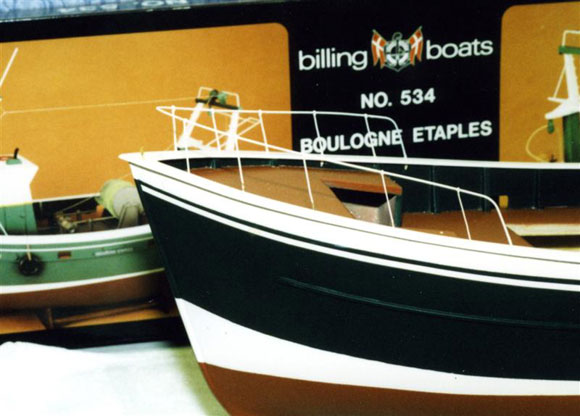
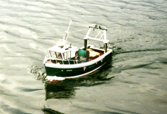
PaintingAll wooden parts that had not previously been treated with sanding sealer, were now painted with a first coat, diluted 30% with cellulose thinners. This was rubbed down and another couple of normal coats applied until the finish was satisfactory. When this had completely dried, I sprayed all the parts with Halford’s white acrylic primer. Blue Tack is ideal for holding small parts whilst they are sprayed. I masked the hull and applied the various colours, using Halford’s acrylic car sprays. Some parts were best painted with a brush using suitable Humbrol paints. For the white line I used car lining tape which is self adhesive. It took me a couple of weeks to get all the painting completed, after which I gave everything a final spray coat of Humbrol matt varnish. This ‘toned down’ the gloss finish. The windows could now be glued in place followed by the wheelhouse roof. The one piece rail I made earlier was now fixed to the bulwarks with 24hr Araldite. When the glue was properly set I marked out the holes for the bow guard rail and drilled suitable holes. I inserted the stanchions and bent them to the angle shown on the plan. The wire was bent to shape, the stanchions removed and threaded on to it. They were then placed in position and soldered. I removed them again for spraying and finally glued them in position with superglue, Photo 15. Instead of using the transfers supplied, I used Letraset, which gives a better result, as it is difficult to hide the ‘film’ of the decal supplied. These were then sprayed with matt vanish for protection. The wiring was connected and all the other parts were then glued in position. Testing and sailingBath time had arrived! I placed the boat careful in the water so that it could be trimmed. It had a slight list to starboard and was a little light. For ballast I used lead sheet that I had left over from roof repairs. This is ideal as the sheet can be easily cut and bent to fit the shape of the hull. Once the correct amount and position had been established I glued it in place using silicon bath sealant. The next stage was to take it over to the club lake for trials. The weather was quite good with only a moderate breeze. All functions were checked and the boat put in the water. She performed well, with a good turn of speed. The turning circle was tight, but like most real boats reversing was more by luck than judgement. ConclusionI have used the techniques gained from building several models and advice from club members. I am sure that there are other methods, possibly better, but the finished boat turned out well enough in the end. As previously stated, the instructions are fine for someone who has built a boat before, but are maybe lacking in detail for a first time builder. The quality of the wood is excellent in most cases, except for some of the ply which does tend to warp and is open grained. I must admit to having enjoyed building this boat. There is a sense of achievement in seeing the hull grow from bits of wood into a nice shape. Considering that it can be purchased at cost of just over £100 for the kit and fittings, I feel it is excellent value for money. For those considering building for the first time, you should remember to add another £100 for a basic radio, motor and speed controller etc., but these can of course be transferred and used in your next boat.
|
Boulogne Etaples
Enjoy more Model Boats Magazine reading every month. Click here to subscribe.
Article Tags:

