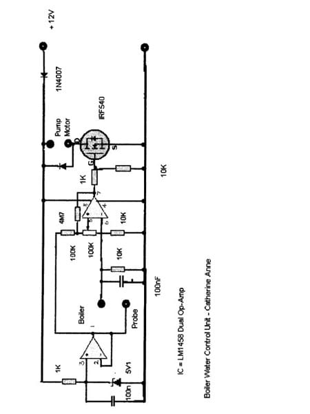
Whilst most steam enthusiasts will be familiar with steam plants in general and associated items such as hand pumps, clack valves, etc., electronically controlled motor driven boiler pumps, although desirable, remain a mystery. The intention of this article is to encourage the building of a simple control unit and also the production of a suitable sensor probe for the boiler using readily available materials. Although the use of a small lathe is desirable for the production of the probe it is by no means essential. The control unit is based upon an 8-pin Dual-In-Line (DIL) dual operational amplifier type LM1458 that are readily available for about 50p. A FET power transistor carries out the pump motor control, almost any will do but the circuit uses an IRF540, which has a proven record and is easily obtainable.
Tools
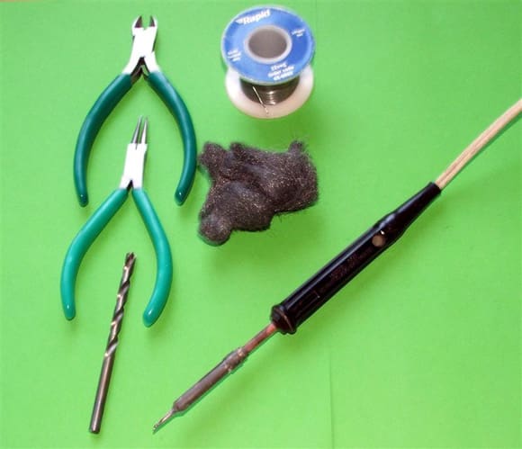
The unit can be constructed using a small soldering iron, a pair of small long nose pliers, a small pair of side cutters, 3/16in (5mm) twist drill (for cutting the tracks), some 22swg solder and a piece of fine wire wool or scouring pad to clean the copper clad board. See Photo 1.
The General Circuit
For those of you not familiar with IC’s (chips) the numbering system is simple. If you look carefully at the chip with legs down and the markings upper most, you will see either a small cut out at the top or a dot near one pin. Rotate the chip so the cut out is at the top or the dot is at the top on the left hand side. This is pin 1, the next is pin 2, then 3 and at the bottom on the left hand side pin 4. Now cross over (still at the bottom) this is pin 5 working up to 8.This will be at the top right hand side opposite pin 1.
Enjoy more Model Boats Magazine reading.
Click here to subscribe & save.
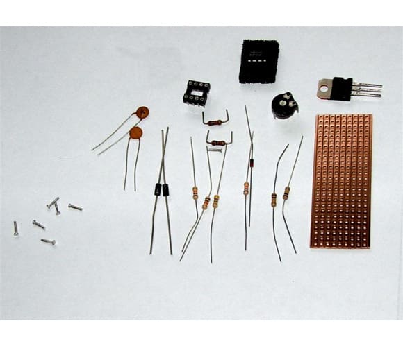
Components
2 x 1K 0.25W resistor (brown black red)
3 x 10K 0.25W resistor (brown black orange)
1 x 100K 0.25W resistor (brown black yellow)
4M7 0.25W resistor (yellow purple green)
1 x 100K horizontal skeleton potentiometer
(All the fixed resistors will have an additional colour band – usually red, silver or gold – this is the tolerance and can be ignored)
2 x 100nF capacitor (104)
1 x 5v1 400mW zener diode
2 x 1N4007 diode
1 x IRF540 FET
6 x Vero pins
See Photo 2
Description
One amplifier is wired as a unity gain 5.1 volt regulator to provide a stable reference voltage to the boiler – probe arrangement and the comparator. The second amplifier acts as a voltage comparator, which compares the voltage on the probe with that set by the potentiometer. If the probe is out of the boiler water the comparator switches the FET switching transistor hard on allowing the motor to run. As soon as the boiler water touches the probe the comparator switches off the FET and the motor stops. The 4M7 feedback resistor controls the delay. The 100K potentiometer allows adjustment for various levels of water conductivity.
Construction
The art of good soldering is to have everything clean and free from grease, oil, etc., plus a good hot iron and fine resin cored solder. First clean off the copper side of the board until the copper shines using the wire wool and blow out any debris trapped on the holes. Follow the layout as shown in Photos 3 and 4.
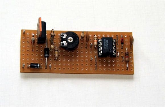
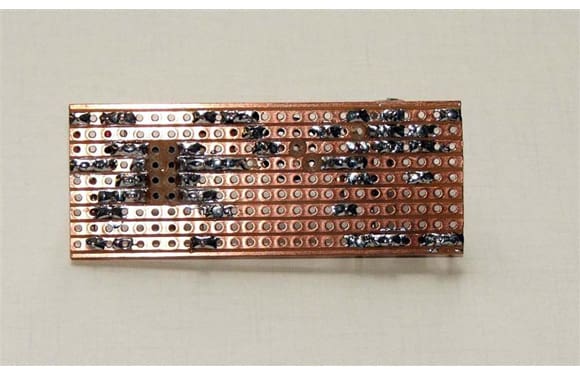
I usually start by mounting the 8-pin DIL chip holder first; this is 3 tracks up, 5 holes in from the LHS (component side). Use the drill between your fingers to cut the 8 holes on the track, fit the holder in place with cut out (or chamfered corner) uppermost to the top of the board. Carefully solder in place ensuring each pin is soldered to the track. Make the top track your positive line and the bottom track your negative or earth line. Follow the diagram and illustrations and things will logically fall into place. Don’t worry about the wire links (such as pin 4 to the bottom track), as the off cuts from the resistors will suffice. Some resistors need bending into a ‘U’ shape to be mounted upright. All resistors and capacitors can mounted anyway round – there is no ‘wrong way’. Mount the Vero pins from the trackside with a firm push and they will lock into place, don’t forget to solder them in on the trackside, (the number of times I’ve failed to do this and then wondered why the circuit doesn’t work!). Insert the LM1458 into the holder ensuring you have it the ‘right way up’.
Finally run a small knife or screwdriver down between the tracks to make sure there are no solder ‘splash overs’ then solder on the motor leads, power leads and the probe leads. I usually use a length of miniature-screened cable using the screen as the boiler connection and the inner to the probe. The next big step is to connect an electric motor and set the potentiometer to approximately mid-point, then switch on the power. The motor should run – if you now short together the probe leads the motor should stop. If it does all is well – if not carefully check for shorts or possibly a missed cut track. I usually finish by making a small wooden box to house the board with a removable lid for any future adjustments.
Boiler Pump and Drive Motor
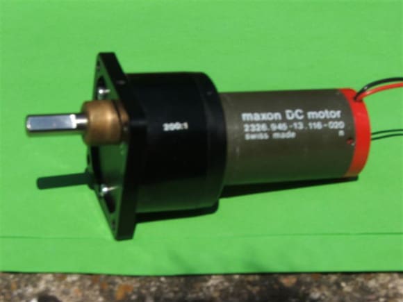
The boiler pump is a standard hand pump as sold by many model engineering suppliers. It is modified by removing the handle and replacing it with a connecting rod and cam arrangement onto the shaft of the motor. The size of your boiler and pump will govern the type and size of the motor you use. If you are going for a small arrangement then I have used a discarded servo with good effect, firstly by removing the electronics and connecting directly to the motor connections. Don’t forget to remove the servo ‘stops’ when you replace the gear chain. The servo arms now make a nice crankshaft for the pump connecting rod. I much prefer to use a motor and gearbox arrangement, these are easily available from model engineering exhibitions and amateur radio rallies. A suitable motor is shown in Photo 5 and this capable of operating a very large boiler pump at relatively high pressures.
Boiler Probe
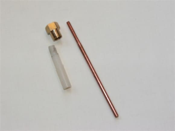
Copper Sensing Electrode. Take a 4in length of 0.125in copper rod and thread to 5BA to a length of 0.875in. If you have not threaded copper before then a word of warning – copper is a soft metal and will work harden, it then becomes brittle and snaps off! When threading, open the die to its furthest extent, apply lots of light oil and gently cut the thread for the required length. Repeat the procedure and re-adjust the die a little each time. After three or four passes you should have a fine thread, If you cannot find 0.125in copper rod then a piece of 3mm will do but you may have to thread it with M3 x0.5 mm die instead.
Brass Assembly Piece
Chuck a piece of 0.375 AF hexagonal brass in a 3-jaw chuck, centre drill and run a No. 12 drill through for about 1in. Drill with a No. 2 drill for a depth of 0.25in, then carefully tap using a 1/4 x 32 ME tap (Model Engineers), finishing off with a 1/4 x 32 ME plug tap. Next run a No. 6 drill though to about 1in. Carefully turn down to 0.3125in for a length of 0.25in and finally thread to 5/16 x 32 ME (you could use 5/16 x 26 tpi or even 8mm as this is the final thread to screw into the boiler). Part off to 0.5in long.
PTFE Insulation Piece
Chuck a piece of 1/4in PTFE in the chuck and thread to 1/4 x 32 ME for a length of 0.3in. Centre drill and run a No. 37 tapping drill down for 0.5in then tap with 5BA (If you are using 3mm copper rod then use a2.5mm tapping drill and tap to M3 x 0.5mm). Finally turn the end to 0.20in for 0.12in. While the PTFE is still in the chuck screw on the Brass Assembly Piece (the PTFE insulation should protrude through the end, if not then turn off a little more until it does.) Part off using a hacksaw. See Photo 6.
Final Assembly
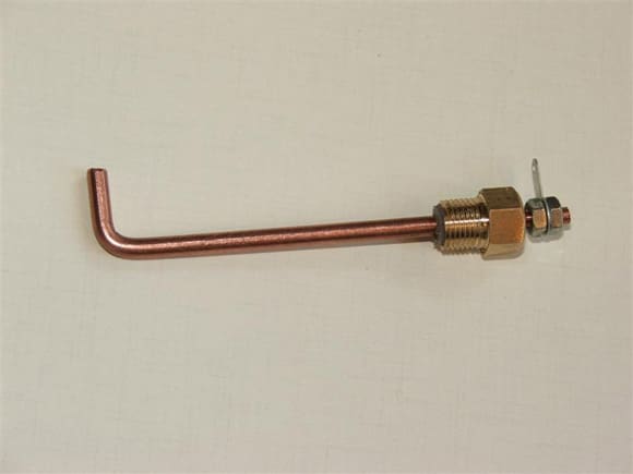
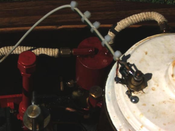
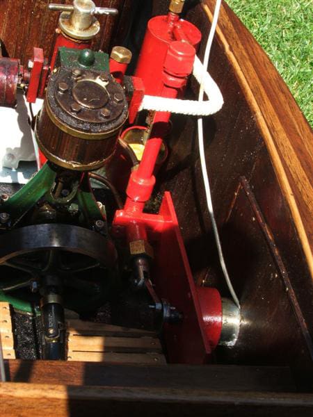
Screw the threaded section of the copper sensing electrode into the PTFE insulation; the threaded section should protrude nicely through the end to allow you to fit nuts and a solder tag. Note: PTFE has a higher rate of expansion to brass and will make a very effective steam proof seal. See Photo 7. Once the boiler probe has been installed and the pipe work made from inlet feed to boiler (I usually feed direct from the boating lake), and the electrical connections made from the control unit to the pump motor and final connection to a battery supply via an ON-OFF switch, the unit is ready to use. The pump should pump water until the boiler water level reaches the boiler probe.
By watching the water level in the sight glass and also tilting the boiler slightly and adjusting the sensitivity potentiometer the unit can be made to switch very reliably. Once set this pot rarely needs adjustment. See Photos 8 & 9.
The control unit is easy to adjust and a kit of parts is available at £2.50 plus £1.75 from Bowood Electronics Limited, 7 Bakewell Road, Baslow, Bakewell, Derbyshire DE45 1RE. Tel: 01246 200222. Website: www.bowood-electronics.co.uk. Just mention ‘Boiler Control Unit as published in Model Boats.’
For metal items and hand pumps, etc., I suggest GLR Distributors Ltd., Unit 1C, Geddings Road, Hoddesdon, Herts. EN11 0NT. Tel: 01992 740098. Website: www.modelmakingsupplies.co.uk.