Avenger
TERRY SMALL reviews the Metcalf Mouldings Tug Kit
Enjoy more Model Boats Magazine reading in the monthly magazine.
Click here to subscribe & save.
Two sister tugs, Avenger built in 1962 and Hibernia built in 1963, were constructed by Cochrane's of Selby for the Ship Towage Group. They were designed specifically to handle the (for then) large tankers of up to 20000 tons, using the terminal at Shell Haven in the Thames Estuary. The most significant feature of the two tugs was the large fire monitor platform high above the wheelhouse. The four fire monitors were capable of delivering 3000 gallons of foam or water per minute. Design of the tugs was of traditional Thames style with a single British Polar M49M diesel rated at 2250hp enabling a bollard pull of 20 tons and a top speed of over 11 knots.
Both tugs are still in existence today, with Avenger in Canada on the Great Lakes and Hibernia in Greece, but having very different colour schemes and fittings.
The kit
This is the most complex kit yet produced by Metcalf Mouldings, taking many months of research and prototype building to bring to you one of the most detailed and intricate scale model tug kits available today. Scale is 1:32 producing a model that is 45 inches (1140mm) long, with a beam of 12 inches (305mm). Displacement is around 40lbs, so it is no lightweight!
The model, because of its complex nature, requires the builder to have some previous model building experience. It is a comprehensive kit containing everything to complete the model to a very high standard, except the usual glues, paints, motor, battery and r/c system.
The largest and most important parts are a highly detailed GRP mouldings, including the hull with all the plating detail, together with the main superstructure, engine casing, wheelhouse and funnel. Printed styrene sheets are included to construct the deck, coamings and deck supports, various lockers, hatches and other fittings. Vac-formings for the single lifeboat and other fittings are included as well as brass tube and rod, wood strip and dowel, rigging cord, anchor chain, propshaft, a cast propeller and over 540 accurately cast and well detailed white metal fittings. Scale keyed and numbered general arrangement drawings, together with a comprehensive illustrated construction manual, complete what's in the box, Photo 1.
Stand
Building a sturdy boat stand for such a big and heavy model has to be the first task and within the instructions, templates and a suitable plan are supplied. Plywood or MDF can be used, but ideally 10mm thick plywood pieces glued and screwed together will be best. Why? Well MDF emits a horrible health affecting dust when cut on a jigsaw and it needs waterproofing, because otherwise at the first sign of water it starts to expand. Once complete, the stand was checked that the hull would actually fit on it properly and then it was was given three good coats of varnish as protection. Personally I prefer the traditional polyurethane type of varnish, but appreciate these are not always available locally nowadays. Photo 2 is of the completed model on its stand. You will notice that the stand is marked 'B' and 'S'. The hull shape is only slightly different at the bow end to the stern ends of the stand, so this makes it foolproof. Dusters are used to protect the hull from the stand, but only because I didn't have a redundant computer mouse mat to hand that could be cut up and glued to the plywood upright hull supports.
Hull and running gear
The hull was inspected for any defects such as small blow holes or mould marks. These were easily resolved, either by filling with Isopon P38 car body filler, or by careful sanding. Such minor defects are quite normal, especially on hull mouldings with plating detail.
At this point, there are a number of things that will need to be done, but they can be done in any order. For example all the freeing ports will need to be opened out. The rudder, propshaft and motor mount will need to be installed and it will be handy to determine the rudder servo position and its linkage before the deck is added to the hull. All of these can be done, together, or in sequence as you wish.
Freeing ports
Cutting these out is dusty work, so maybe is best done outside. The various sections to be cut-out on the hull are already marked on the hull, but highlighting their perimeters with a pencil is no bad thing. They were then chain drilled as appropriate, the holes joined to make small openings which were then then filed to shape as in Photo 3. The hawse hole openings were done in much the same way, although chain drilling is not really necessary for these.
Rudder
The rudder and its skeg are fixed in position as in Photo 4. Assembling the rudder was very easy from the styrene and white metal fittings supplied. It is however, very important to get the rudder to sit perfectly upright and be able to turn easily from the extremes of its port and starboard movement. The actual rudder blade also has to be shaped on its aft outer flank faces to a sort of mild aerofoil section. The rudder is hung on pintles, with its stock offset which then bends back, to come in line with the pintles, otherwise the rudder won't turn! Anyway, on the basis that a picture tells a thousand words, Photo 5 shows the final finished and painted result and how it should all look.
Propshaft
Fitting the propshaft requires a hole drilling through the centre of the outlet boss on the hull and then being opened-out, before fitting the rudder. If you refer back to Photo 4, you can just see where clumsy me did manage to break away part of the GRP boss, so into action with the filler later! The propshaft is not supplied with an oiler tube, so one was added as in Photo 6. Easy enough; just drill a hole in the propshaft tube (with the threaded propshaft itself removed), insert a piece of dowel or similar into the hole and slide over it a piece of spare brass tubing, with its lower end shaped to match the circumference of the propshaft tube, and solder in place.
Before gluing the propshaft tube in position, it is also not a bad idea to decide which propeller size and type of motor will be used. A brass three bladed 70mm diameter propeller was chosen as an alternative to the cast version, together with a 6v Marx Hectoperm 2:1 geared motor. Not cheap, but these motors are known for their power, plus long and reliable service. A 12v version might have been better as the model can easily accommodate this voltage of Sealed Lead Acid (SLA) battery which would be bigger and heavier than the 6v type and would therefore assist with ballasting. The solution later turned out to be simple, as two 6v SLA batteries could be easily installed, either wired in parallel or with one as a spare.
Rudder servo
The rudder servo and its linkages are shown in Photo 7. This picture also shows the propshaft glued in position and some of the deck edge support stringers and deck beams. Also, note the short piece of plastic tube creating a secure solid glue mounting for the rudder post tube.
Motor mount baseplate
This was cut from scrap wood and shaped to fit neatly into the hull as in Photo 8. A slight angle is required of the propshaft which can be set by adjusting the motor base.
Bilge keels
These should be added either side of the hull as indicated on the plan and they need to be pinned and glued for a strong fit. Having said that, you will notice from the photos that this model does not have them! Not because I forgot to fit them, but because I just did not like the look of them and to be perfectly honest there have been no stability problems with the model on the water as a result. So, 'sorry' to Dave Metcalf for omitting the bilge keels, but they are not essential if you are not too bothered about being 100% true scale.
Main deck and bulwarks
I have already given the game away if you refer back to Photos 7 and 8 which show the concept. Basically there is a built up deck edge stringer glued to the inside of the hull, just below the lower line of the freeing ports, built-up deck beams are inserted across the hull and then the two main sub-deck sections glued down onto the stringers and deck beams. Now for the detail of what to do!
Deck edge stringer
The usual method is employed of gluing two lengths of 3 x 6mm styrene strip all around the inside of the hull 2mm lower than the bottom edges of the freeing ports to allow for the deck thickness. It’s best to sand the inside of the GRP hull first to obtain a good keying surface. The first stringer layer was glued with medium viscosity superglue to the GRP followed by the second layer glued over the first layer with traditional styrene cement (like we used to use with Airfix kits). A deck beam layout and how to assemble each of them into an H section is clearly shown in the instructions together with their sizes. As you can see from the photos, a fillet of Isopon P38 filler helps create a better joint.
Deck
Before fitting this, a couple of layers of Isopon P38 filler, applied to the inner face of the hull above the deck stringers and then sanded smooth, will make the inside of the bulwarks look neat. Some may prefer to do this after fitting the deck – it is a matter of personal choice.
The deck is actually in two half-sections, port and starboard, with the joint line going down the middle of the model from bow to the stern. These sections will need slight trimming to achieve a perfect fit before being glued in place with weights and/or clamps holding them down until the adhesive has set. The inevitable Isopon P38 filler then applied between the deck edge and hull sides, then sanded smooth, will fill any small gaps nicely. The deck openings have coaming strips around them that need to be fitted and glued in place. Nothing unusual here from a construction point of view, but they are important as they add rigidity to the deck as a whole.
Deck plating
The deck has simulated plating in the form of rectangular styrene plates. These need to be cut to size, following the plan and instructions, with their top edges which represent the plating joints being scraped to a slight angle by dragging the cutting edge of a Stanley knife blade along them. The best way to glue these plates down is to apply a limited amount of liquid styrene glue applied with a brush to the edges of each plate once in position on the sub-deck. Admittedly there may not be much glue underneath the centre of each plate, but they are all firmly stuck down and have shown no signs of coming off or lifting, even when in sunlight. Photo 9 shows an area of such plating and some bulwark supports as in the following section.
Bulwark uprights and capping rail
There are a total of 56 bulwark supports to be individually cut from their carrier sheet, carefully noting where they go depending on their sizes. Shaping and smoothing their edges is best done before being glued in place, as this is easier now than later. So, yes a bit tedious, but it is worth doing well and actually only takes a couple of long(ish) evening 'workshop' sessions. At the bows and spaced along the sides are additional supports for the bollards as in Photo 10. Thin superglue was used to glue each bulwark upright in position as well as the capping rail which is in sections and is supplied slightly oversize, so it can be sanded to a neat regular width all round the model. Photo 11 shows a completed and painted area of deck, to show how it will look when finally finished.
External bulwark detail
White metal fittings such as the bars across the freeing ports, hawse hole surrounds and deck drains will need to be fitted as in Photo 12. This is one of the more pleasant things about 'kit bashing' as you can make rapid progress in an evening, and the model will look different to what it did the previous day, which can be quite motivating. Photo 13 is a close-up of the painted port bow section with hawse hole and freeing port bars added. This also shows shows the plating detail on the GRP hull which is really quite realistic.
Lower superstructure, wheelhouse and funnel
As you will have seen in the kit contents picture, GRP mouldings for the lower main superstructure, enclosed wheelhouse and the funnel are supplied. These are all of good quality, but the main lower part will, in particular, require carefully sanding and trimming to follow the deck camber.
Lower superstructure unit
Holes for the portholes together with door openings will need to be cut out as well as trimming its lower edge as in Photo 14. Rather handily, there is a raised strip around where this unit meets the deck, so that is as good as any a line to follow initially, and in fact final sanding is actually quite minimal – so well done Metcalf Mouldings! In the case of the doors, if it is to be open, then a hole has to be made. If closed, then the door can simply be glued into the moulded mark position. Mind you, if the you are having an open door, then some interior detail will be required.
When opening out portholes, drill a small hole first and then open out with a tapered reamer or similar. Try not to 'pull' the reamer or file from the inside to the outside, as the GRP gel coat can be easily pulled away from the 'lay-up coat' if you are too vigorous when filing.
The top deck of this unit overhangs the main body and is cut from a printed styrene sheet and will need to be glued to the top of the GRP moulding. A thin layer of epoxy applied to the interface and weighting down until the glue has fully cured as in Photo 15 is what is necessary. The secret to a strong solid glue joint for styrene to GRP is to thoroughly key both the contact surfaces using a medium abrasive sandpaper.
Wheelhouse
Again, a well detail decent GRP moulding. The windows will need to be cut out and frames made for them from 0.5mm styrene strip as explained in the instructions, Photo 16. However, the funnel fits into the rear of this unit, so that has to be installed before we go much further.
Funnel
This GRP moulding is a very well detailed with all the plating detail. It only required an all over light sanding to remove any small blemishes. The plan shows the funnel sitting at a slight backwards rake and partly over the rear of the wheelhouse unit, so some marking, followed by cutting is required, much simplified if you follow the instructions! Photo 17 shows this cutting having been done with a junior hacksaw. It is best to permanently fix the funnel to the wheelhouse moulding by shaping a block of wood to fit inside the bottom part of the funnel that will rest on the wheelhouse moulding to act as a mounting piece so that it can all be glued and screwed together.
The funnel top has a recessed printed styrene plate glued within it and again, it’s a job of shaping the plate to fit snugly on a ledge made from 3 x 6mm styrene strip, Photos 18 and 19. A small piece of aluminium mesh from the 'Bits Box' will make for a nice funnel top covering grill, if you wish.
Companionways
On either side of the lower superstructure are two companionways. Rectangular holes will need cutting out of the upper deck of the lower superstructure unit, after which the stairwells are assembled from printed styrene parts, Photo 20, and glued in place as in Photo 21, which is of the whole thing, but upside down. Photo 22 is of the completed and painted port companionway area with its steps from the main deck ending just in front of the funnel behind the wheelhouse.
Engine room casing
This is a simple box shape GRP moulding, but once again has well moulded detail, Photo 23, but it also requires trimming to size by using a razor saw or cutting disc, a Dremel tool being my preference. Drilling and cutting GRP is a dusty task, so wearing a mask and protective glasses is a good idea. The centre top skylight section of the moulding will also need to be removed and chain drilling a series of 3mm holes and then joining them will remove the bulk of unwanted GRP, followed by filing and sanding to the final shape.
The skylights themselves are assembled from printed styrene parts as in Photo 24 and they fit over a sort of shed roof type of unit that fits over the opening we have just made in the engine room casing. The skylights can be open or closed, as you desire, and bearing in mind this model is large, there is no reason why a sound generator speaker could not be installed just underneath them. Remember this was a diesel tug as built, so fitting a steam engine would not be pro-typical, assuming you are building Avenger as a scale model. On the other hand, some readers might see the kit as suitable for a steam plant because of the model's volume and displacement capabilities.
There are also various lockers and fittings to be added to the engine room casing as in Photo 25, and Photo 26 shows the completely finished and painted item.
Monitor platform
When choosing a subject to build there has to be something about the full size craft that attracts the model maker. In the case of Avenger, it is the huge platform with four big red water monitors from which the real tug could deliver 3000 gallons of foam or water every minute. There is no doubt that most kit purchasers will want to have the monitors working, so before the platform itself is assembled, a manifold for water delivery to each of them has to be made from the supplied brass tube, cut to size and soldered together, once again following the plan and exploded drawing. If soldering is not your cup of tea, then small plastic Y-tube joints can be used instead which can be obtained from Squires Tools or Hobbies. They are also very much the same type as used in domestic tropical fish tanks, so retailers for these are an alternative source. The manifold, once complete, has to be fitted to the underside of the platform as in Photo 27.
This platform is the key part when constructing the mast, steps and A frames and all has to be in perfect symmetry from all perspectives. So, the whole thing requires some care in construction and from a practical point of view, final assembly is best on the model and before painting the superstructure. It is not easy to construct, Photo 28, and yes, the angles are correct. Soldering the support tubes together is best, but with a little ingenuity, gluing and pinning could possibly work, but I used the former method.
The water cannons have been designed to work, hence a length of silicone tube is supplied. A 6 or 12v pump can easily fit in the hull, drawing water externally and pumping via tubing up one of the platform supports into the manifold and thence to the monitors. These can be fixed and set at varying angles 'of attack' or no doubt with a little ingenuity be made to traverse, Photo 29. The monitors are themselves well detailed, but require some assembly to complete. On that subject, some figures operating them wouldn't be a bad idea as well. I am increasingly coming to the view that Marie Celeste (i.e. no crew) type models can look a bit odd nowadays, particularly at this 1:32 scale.
Fittings
As I wrote earlier, there are over 540 cast white metal fittings in this kit and they usually require just a slight amount of fettling with fine sandpaper or a light scrape with a Stanley knife blade followed by a polish with a suede brush to remove any flashing and preparation for painting.
An example of a mini-kit within the whole kit is the anchor winch. Photo 31 is a picture of it unpainted and Photo 32 is of it finished, painted and in place on the model. A high strength superglue was used to secure each white metal to another and is as good a means as any of holding it all together. You could use low temperature solder with a suitable iron, but as the item is not actually load bearing, superglue is good enough. The pivoting tow hook, Photo 33, is another such item that requires careful assembly.
The davits for the single lifeboat are accurately cast, Photo 34. Mounting pins were inserted into their feet to ensure positive location on the superstructure as in Photo 35, this last picture also showing the lifeboat which is based around a vac-formed hull and is a mini-kit in its own right.
Railings
Two types of white metal stanchions are supplied, two and three hole, each requiring very little cleaning up, but quite fragile and broken if bent too much. Some of the holes may need opening out to accept the brass rod supplied. Each stanchion has a moulded in mounting pin at its base which will fit into a locating hole drilled in the decks. Spacing and exact positioning of these is measured from the full size plan. It’s better to drill the mounting holes slightly smaller than the diameter of the pins to ensure a positive positioning. The brass rod for the actual rails has to be bent as necessary and passed through the stanchions and then either soldered with low temperature solder or glued with a good quality superglue. Bondloc from the Maplins electronic store chain seems to be very good. Photo 36 shows the unpainted stanchions and handrails on the wheelhouse deck.
Wood?
Yes, you read correctly! This model is not all plastic, GRP and metal. It has some of that old fashioned material called wood, namely dowel for the mast and mahogany strip. The dowel is easily finished by applying three or four coats of sanding sealer, lightly sanded between coats. It will need to be shaped for the mast though.
The mahogany strip is used on the open bridge, and other places on the model. One wonders if there is any wood at all in some modern 21st century vessels. Three coats of Ronseal clear satin varnish, lightly sanded between coats was applied to a strip of mahogany, before cutting to length as the location dictated, Photo 37. The actual application of these planks to the model is best done after painting the main superstructure body and superglue will hold down the individual mahogany strips very nicely. The pieces were 'mixed and matched' from different strips, thus creating a rather nice effect as all the strips are not exactly the same mahogany colour, but are the same, if you understand what I mean.
To get the individual end angles correct, a small model maker's bevel gauge from Squires Tools was handy. Where the vertical planks curve around the wheelhouse front, the edges of each were sanded to an angle to obtain a better butt joint. Once all the mahogany was in place, it was all given another coat of varnish.
The slatted flooring in the open upper steering position and at the stern, Photo 38, follows much the same process, but is spaced out on bearers.
Glazing
A sheet of clear styrene sheet is supplied for glazing the superstructure window frames and portholes and the windscreen on the upper bridge. Care must be taken when gluing the individual sections behind the window frames and for the windscreen.
Painting
Preparation to ensure paint adheres to GRP and styrene is very important. Always wash everything using mild soapy water (except wooden parts) and endeavour to remove all grease, dust and finger marks. Also, keying the 'to be painted' surfaces by rubbing down with 600 grit wet and dry sandpaper making sure not to remove any fine detail, should ensure a good 'key' for the paint.
The hull and deck are painted with Halford's acrylic spray satin black and red primer. As for the superstructure, there was no direct Halford's spray equivalent to Humbrol No. 9 Brown, so this enamel colour was sprayed using a trusty Badger 150 airbrush.
The fittings were mounted on scrap wood strips and sprayed in batches, depending on the colour. A final all-over protective thinned satin varnish coat was applied by airbrush after final assembly and addition of the tug's name etc.
Radio control and ballast
The simplest requirement is for a two channel system for just rudder and motor control. An ACTion R/C electronics Condor 20/2 20 amp Autoset fully proportional electronic speed controller is more than adequate for the Hectoperm motor (ACTion units are now retailed by Component Shop). If you want to have working fire monitors and a pump, then additional channels will be required. The rudder servo is of the standard type – powerful enough for this model as it so happens. Battery power is supplied from two large (and heavy!) 6v 10Ah SLA batteries wired in parallel. If wired in series, then power output would be 12v. The receiver is mounted on the inside of the coaming with double sided tape and Photo 39 gives you an idea of the final internal layout. You can also see the bags of lead shot ballast which naturally take the shape of the hull. In my experience with large and heavy models, this is the easiest way of having removable ballast. Provided the bags are labelled and a diagram made of their locations, then they can easily be removed for ease of transport and/or transferred to another model. Avenger has an all-up weight of around 40lbs (18kg).
On the water
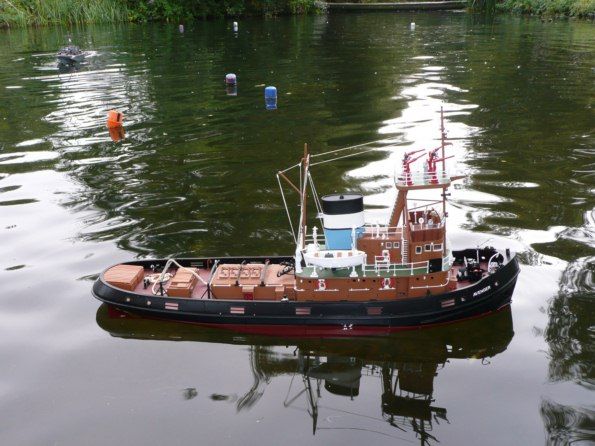
The 6v geared motor turning the large propeller proved more than adequate for the task, Photo 40. Turning circle with the rudder full over, was about 1.5 times the model's length. Astern control was very good for a single screw model and maximum speed was over-scale, so plenty in hand there.
Conclusion
A nice well detailed model with plenty of construction work to stimulate the model maker's fingers and brain and the parts and materials supplied were all of high quality. Yes, it is a single screw model, but it handled well enough on the water and of course there is plenty of scope for super-detailing, if the purchaser so desires. Price is £350 plus p&p, which is excellent value for money judging by the prices of some kits nowadays, but it is a kit for those with some experience within the hobby. It is only available direct from Metcalf Mouldings, tel: 01920 438686, website: www.metcalf-mouldings.com. Please see their regular advertisement in this magazine for further information about the whole product range.
A selection of detail, finished and on the water images of this impressive model are shown below.