ACTion P94 review
JOHN ELSY builds this twin electronic speed controller and mixer unit
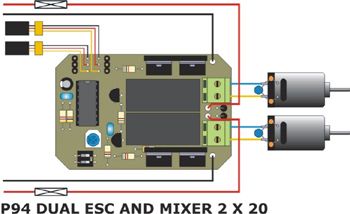
Diagram showing application of the P94 Unit
In all hobbies there are one or two areas where many of us fear to tread and in our model boating hobby, one of these is electronics. This can put a lot of us off from building and installing electronic kits, so to try and dispel these fears, here I will endeavour to boost your confidence. Anyone who is capable of producing a good soldered joint can extend their abilities and knowledge by completing one or two electronic self-assembly kits.
This kit is from ACTion R/C Electronics who have been around since 1994 building and selling electronic gizmos for the model boat market. Much of the range is available as kits as well as ‘ready to go’.
Enjoy more Model Boats Magazine reading in the monthly magazine.
Click here to subscribe & save.
So, this is the P94 twin speed controller and mixer, all in one compact unit, length 74mm, width 50mm and height of 58mm (to the top of the heat sinks). There are currently two versions; the 20 amp P94 and the 10 amp P94 Lite version which does not need heat sinks so is only 30mm high, but otherwise is the same size. Photo 1 has the ACTion kit as supplied.
What do you get?
There is also the plastic case and inside it you will find the printed circuit board and relays. Photo 2 is of all the components, but you are best advised to keep the transistors and i.c. chip in the anti-static bag until needed. Note also that in this picture the Power Mosfets are not fitted to their heat sinks. There is some variation in packing arrangements depending on the ACTion mood at the time!
Tools required
Photo 3 gives an idea of what is required.
A 25 Watt soldering iron with a 3mm flat screwdriver tip will do the job but a 15 Watt soldering iron is a safer bet for the smaller components and better still would be a soldering station, but that’s not essential.
Flux cored solder, 22 SWG (0.711mm dia. is recommended).
Small pair of wire side cutters.
Small long nosed pliers.
Spring locking tweezers.
Small flat blade screw driver.
A magnifying glass is handy.
A small crocodile clip as a heat shunt when soldering sensitive components.
Three or four small plastic containers for storing and keeping safe the individual components (small plastic sweet or food containers are ideal).
A multimeter is handy for testing, but is not essential.
Before starting
Before we start soldering there are a few golden rules!
1) Read the instructions!
2) Static electricity can harm some electrical components, so we must avoid this. Nylon clothing is a natural generator of static as are nylon carpets, so it is best to try and avoid this occurring.
3) A good level of light is essential and a desk lamp may help.
The instructions are laid out so that someone with little knowledge of electrical components will easily understand them as each component is described in complete detail, so once thoroughly familiarised, we can begin.
First step
The important thing to watch for when soldering the socket in place is not to bridge the pins with solder as the pins are very close together. So please double check this component once fitted and soldered.
Fitting the capacitors
In this kit there are two types; monolithic and electrolytic, and the total number of capacitors in the unit are three.
There are two monolithic and these are a bit like resistors in that they can be fitted either way around and are not too heat sensitive, but prolonged heat will destroy them. These are light blue in the photographs.
To help fit the electrolytic capacitor correctly, locate the holes in the circuit board and then using the component layout diagram as a reference guide, mark the negative hole with a felt tip pen. Photo 8 has the three capacitors fitted, the two light blue components being the monolithic capacitators.
Fitting the two diodes
Diodes can come in all shapes and sizes, but the ones in this kit are cylindrical with a thick wire at each end. They are black in colour with a silver band round one end and this is the positive side. They must be fitted the correct way around, just like the electrolytic capacitor. These diodes are soldered in place vertically on the board and the silver band is uppermost. Photo 9 has them together at the right hand end of the board.
Fitting the two header pins
These are for the rudder servo plug and also a third speed controller, Do ensure that the short ends of the pins and NOT the long ends are soldered into the circuit board, Photo 10.
Time to fit some of the sensitive parts
Mosfet transistors:
DIL switch and variable resistor
14 pin IC socket
Power Mosfets
Relays
Terminal blocks
Power cables
If a 15 Watt soldering iron has been used throughout the assembly, it will not have the heat to solder the 14 swg silicone power supply cables. The trick to getting the tinned end of the cable through the hole in the circuit board is to twist the bare strands tightly, then tin with a 25 Watt soldering iron and once cool, dress the tinned end with a file so that it is a nice fit through the hole. Once the four power cables are fitted, Photo 18, the next step is to reinforce the copper track between the positive (+ve) lead inputs and where the track divides to feed both relays with a piece of 15 amp single strand copper wire, Photo 19.
The last bit of soldering
Fitting the r/c feed cables and plugs
When ordering the kit, specify the type of radio receiver you will be using. This is because ACTion will pre-fit the plugs to the cables. So before you attach the leads don’t forget to fit the little plastic identification collars. One is marked S (steering) the other T (throttle) and please ensure that the cables are in the right order. White is signal, Red is positive power and Black is negative power, Photo 20.
Cleaning up
The track side of the board now has to be cleaned which can be done with a tooth brush and some spirit cleaner. Methylated spirits is good but even better is Isopropyl. Following cleaning and double checking of the solder joints, the 14 pin IC was fitted.
Now clean the work area so that you do not put the unit down on top of offcuts of wire by accident and thus short it out when it is powered up!
Testing and set-up
Set the two-way DIL switch for Mode 4 as per the instructions.
Plug the leads marked T and S in to the throttle (T) and rudder (S = steering) channels of a suitable receiver and then switch on the matching transmitter. Now switch on the receiver power supply, move the throttle stick from neutral to full forward and then full reverse and as you do this, listen for the relays ‘clicking’.
If you hear this sound then it proves that this part of assembly is okay.
The main power battery should now be connected to the pc board. Pay particular attention to this as the two main red wires are connected together at the positive terminal on the battery and the black wires are connected together at the negative terminal. Set the throttle stick to neutral, switch on the transmitter and then the receiver, and slowly move the throttle stick forward. The motors should work. Now move the rudder stick either to the left or right of centre and one motor will slow down and the other will speed up. So, no complicated multi-meters are needed! If you have soldered correctly, then it will work and that is all the kit builder really needs to know. Photo 21 has everything laid out for bench testing.
The case
All the dimensions are in the instructions and the usual method is to mark them on to the case. One alternative is to photocopy the case cutting diagrams from the instructions, cut them out and attach to the case with PVA glue and use as direct templates. Then cut the holes out, clean the burrs off the edges and remove the templates with warm water. Dry the case thoroughly and fit the unit inside it, Photo 22.
Conclusion
website: www.action-electronics.co.uk.
The P94 20 amp unit is priced at £78 assembled (£75 for the 10 amp ‘Lite’ version), but it is 15% less when supplied in kit form.