MICHAEL J SHEPPARD describes his working model
I have with this article decided to use the text to explain the pictures. I hope from this that you will be able to see how I made this paddling Indian Canoe and that it might inspire you to have a go at something a bit different.
Photo 1
Enjoy more Model Boats Magazine reading in the monthly magazine.
Click here to subscribe & save.
I’d not seriously considered this style of paddler as a project for my expanding fleet of rowers and paddlers until one day whilst doodling with a pencil, it became clear that if the cranks could be made stiff enough from a sideways twisting motion, it would be a practical proposition. Some sketches quickly followed, sorting out the more obvious kinks and weaknesses that came to mind until a basic design evolved.
Photo 2
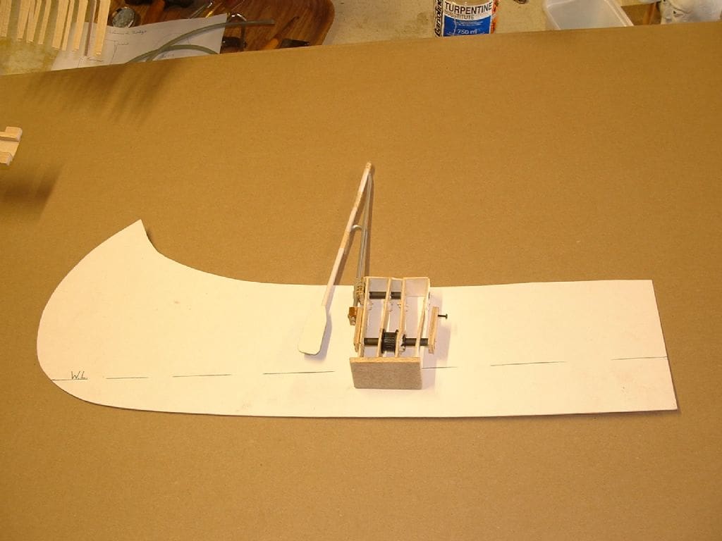
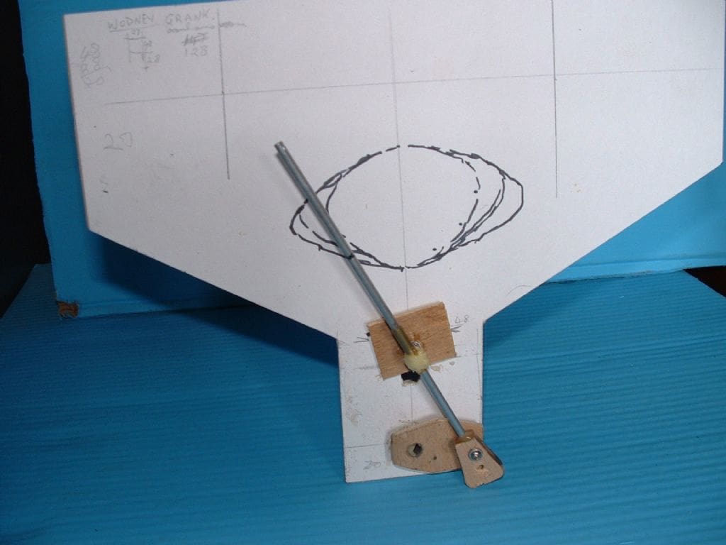
Firstly I made a mock-up of the Mk.1 paddler unit which was simply made from scraps of Lite ply, alloy tube and bits-and-bobs. At that time it was intended that the general pattern followed my accepted pattern of using a toothed belt drive. The absolute essential of this unit as I saw it, was that somehow the crank rods must not twist and jam in the cam slide tubes. At first it seemed practical, so a prototype unit was constructed and then the problems started. Because this time there was no sloppy give in the mechanics, it quickly jammed solid when even a slight pressure was applied to the paddle blade, so a rethink was necessary.
The picture also shows how the canoe hull depth was established by putting the paddle unit on a piece of card and drawing around it. Now my research into these canoes had established the fact as to just how shallow they are. Many examples of old canoes in museums were from 8 to 12 feet long, 30 inches wide and just 8 inches deep. There was no way I could get a mechanical paddle unit comfortably in a scale size hull so a compromise was required.
Photo 3
The hull shape had to be reproduced in three dimensions, filled out and with some rocker (curve of the keel).
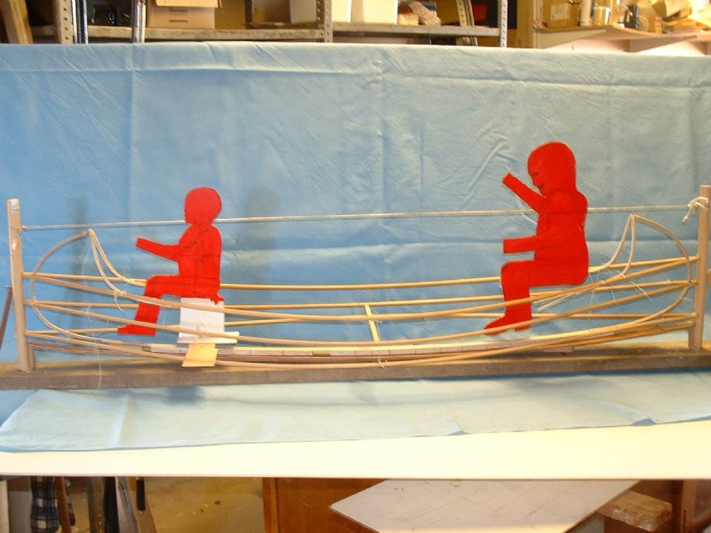
How to actually build the model had been a bit of a brain teaser, particularly as my canoe needed to be deeper than true scale. The frame was made from 6mm Ramin dowel, sprung between two well supported end posts. The two curved stem pieces, made previously from laminated ply strips in a purpose made jig, were tied in place.
Sections of cardboard were then cut and glued together to give me the shape. It took some time, but I got there eventually so that I had a shape to look at. The two crew silhouettes were also produced in card. A female in the bow position and a ‘Davy’ like person in the stern who was later reduced very slightly in size. At this stage I’d had no idea at all as to how I’d go about making either of these figures.
Photo 4
It is essential to work out the stroke length and lift that suits your model. For this I make a dummy crank unit with the facility to alter the distance between crankshaft and camshaft and also the crank length. The closer the crankshaft and camshaft are to one another, so the longer can be the stroke, but for this creation only a modest length is needed.
Photo 5
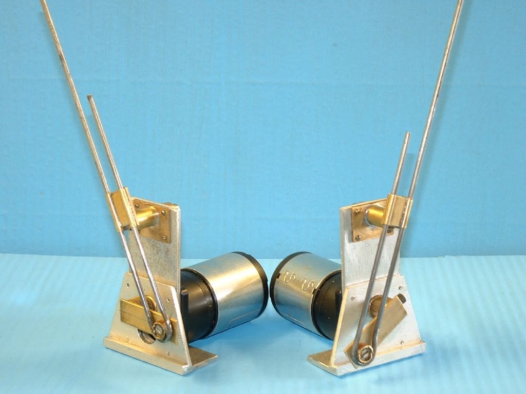
These are the Mk. 2 crank units. The hull proved to be too narrow for a belt drive if the crew were to go in at the prescribed places. You will see that the motor output shaft has become the crankshaft. Note the twin crankrods used in an effort to eliminate twisting and jamming. They work very well, but considerable care and determination is called for in getting them exactly parallel with each other. With this design it is also not possible to alter the final speed by selection of pulleys as there aren’t any!
The Maxon drive motors are truly beautiful little jobs and were supplied by Model Motors Direct.
Photo 6
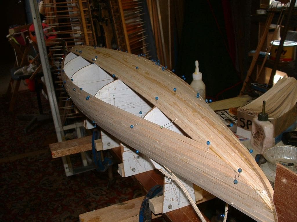
The hull was planked with 3mm balsa over hardboard frames, the edges of which were covered with Sellotape and waxed as a double guard against sticking. How exactly the plank runs should go on a shape such as this I didn’t really know, so I did my own thing. Real canoes were sheathed with birch bark and not animal skins according to my research and were also built right side up on the ground. This planking job seemed to contain more stealers than planks, but a very robust and pleasing enough shape was soon formed. No attempt was made to do a perfect job as it was to be covered with glassfibre sheathing to waterproof it and make it more durable. You will see later how I coloured it to replicate the birch bark. During planking I realised that another two frame shadows at the ends would have been a good idea.
That odd looking thing in the background is my 66 oared galley standing on end in its carrying and storage frame. Yes, it is bolted in with two brass bolts into captive nuts embedded in the keel. It is about five feet away from the canoe, though does not look to be so in the picture.
Photo 7
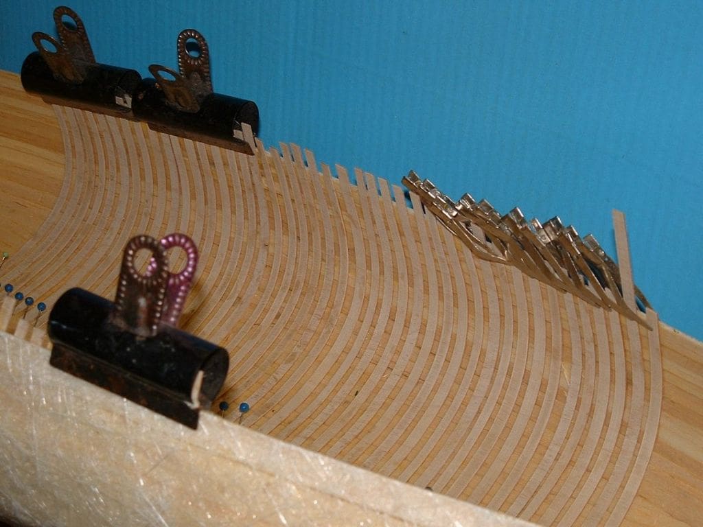
Cross grain cut strips of thin plywood were used to simulate the ribs. In full size canoes, strips of thin, flat and wide wood are laid lengthways between these ribs and the outer bark to stop unsightly rib lines showing through when the bark shrinks.
In my research for this project it was found that early canoes used no nails or rivets. Everything was lashed or notched and bound using tree roots as thonging. Seemingly, the women folk used to chew animal sinews and roots to soften them prior to their men folk lashing together the canoes. Dissolved beeswax was used to waterproof the outside of the canoes.
Photo 8
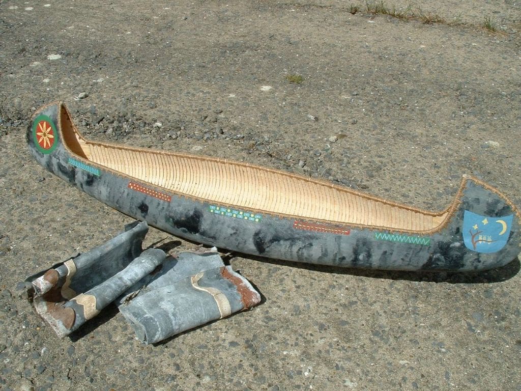
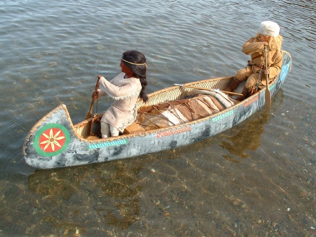
The finished basic hull. The outer coating was done with thin coats of fibreglass resin with three different colour mixes. This I’d hoped would produce a near enough birch bark looking finish. The decoration was done free hand, inspired by illustrations from one of the research books.
A ballast check revealed that the empty hull weighed about 2lbs (a bit less than 1kg) and with temporary lead ballast to float about right it weighed 14lbs, so I guessed that after the mechanical bits were installed about 9lbs of ballast would be finally needed.
Photo 9
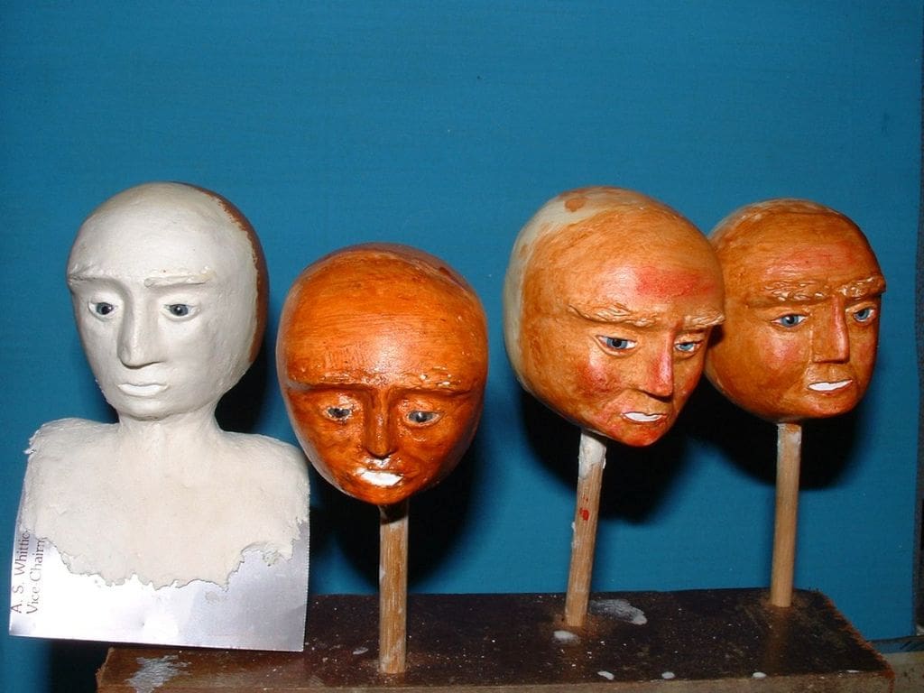
These heads have a polystyrene core and are then covered with some stuff called Model Lite produced in Belgium. I got it from Specialist Crafts Ltd, PO Box 247, Leicester, LE1 9QS, tel: 01162 697711, website: www.specialistcrafts.co.uk. It’s truly wicked stuff to get the hang of in use, but now after some false starts it is my first choice. It must be worked with hands and tools whilst wet. I work over a shallow tray of water dipping the work into it quite often.
The best two and most suitable of these then went go forward to become my crew. The eyes are commercial doll’s eyes and the white teeth are simply pieces of plastic margarine containers glued onto the face before the mouths are shaped. Teeth can be formed by marking with a small sharp blade. For painting figures I tend to use acrylic water soluble paints. I have tried Humbrol enamel but I can’t seem to get it right, but that may just be me. The core subject is painted initially with a few coats of thinned PVA glue as an undercoat and sanded lightly with a fine grit paper. Then a few coats of thinned down base white acrylic are applied, followed by a few of full strength. Again this is lightly sanded with wet or dry paper before the colour coats are applied. I do not claim to be good at faces, but am getting better. The one I’m most pleased with to date is my Eskimo Nell from a few years ago.
Photo 10
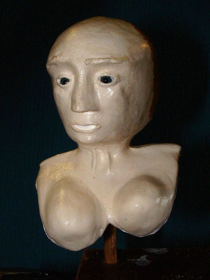
Alas for the female, the research I’d been looking forward too didn’t happen, so I had to fall back on distant memory recall! Her torso base was formed from a piece of my now fast dwindling stock of Litho plate which is a very thin sheet alloy once used extensively in the printing trade before computers. It is still used, but you have to search hard to find a printing firm that uses it.
Photo 11
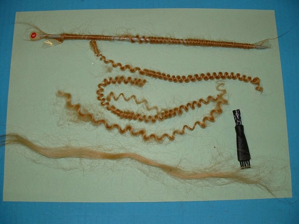
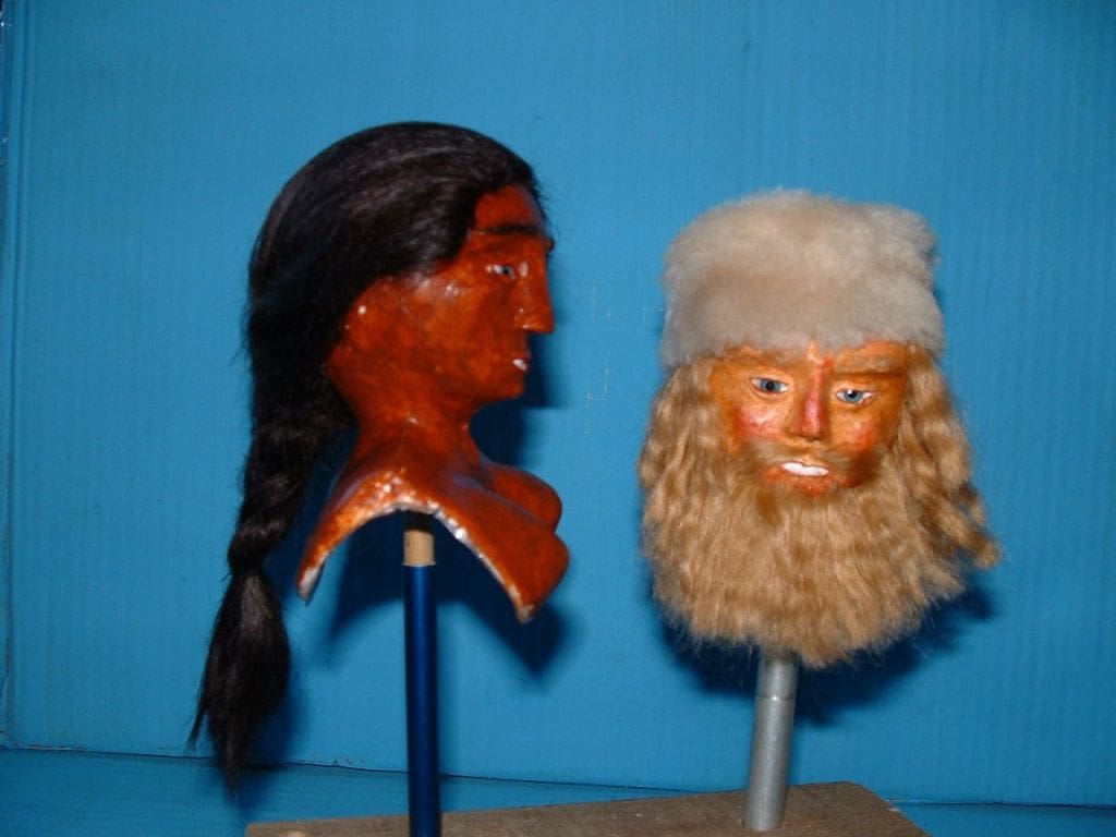
For these models I had another crack at wigging. That’s a term for putting hair strands onto heads and indeed onto the chin as well for a beard. Dolls house suppliers are the place to get it and this came from Dear Dolly Aral Dollmaking Supplies, Southminster Road, Upper Mayland, Chelmsford, CM3 6EB, United Kingdom, tel: 01621 774773, website: www.deardollyaral.com. The choice was; real hair, mohair or some sort of cheaper stuff? Horse hair is also used in some cases. Real hair is as might be expected very pricey and is confined to the very top end of the market. You can also buy readymade mohair wigs, but sizes are rather limited. I bought two half metre hanks of mohair after I’d been assured by the sales person that it had nothing to do with mohair wool to which I am allergic.
The man’s hair is shown in the picture where I’m trying to put some kinks in it.
Photo 12
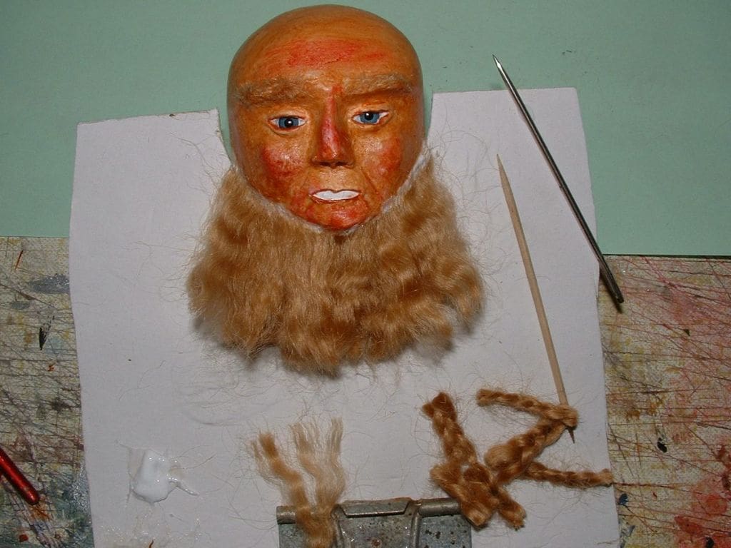
At the bottom you see the eventual method adopted for kinking the hair. It was plaited very tight, steamed and left to dry. This produced a sort of flat wavy effect and in the middle bottom can be seen a section of hair ready for gluing in place to his chin. The glued end needs trimming with a very sharp pair of scissors to match the intended glue line. RC Modeller’s Glue was my choice and the tools were cocktail sticks and a heavy steel bodkin needle, plus a big chunk of patience. The subject needs to be nailed down firmly and that cardboard sort of bib affair was eventually glued in place for the duration. It also came in mighty handy as a sort of bench for materials and tools. This slow painstaking job requires delicate fingers and good light, particularly for dark hair. After all the glue has cured the shaping of the hair can be done. I used a very sharp pair of tiny scissors and snipped at the hair to produce an acceptable shape.
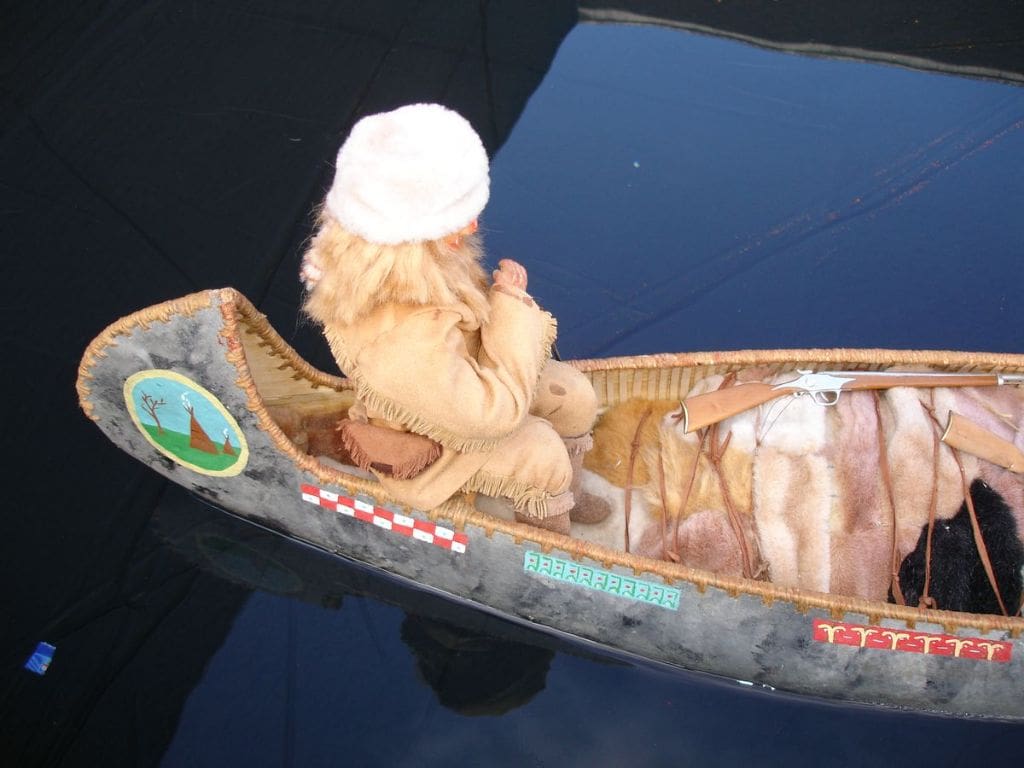
Photo 13
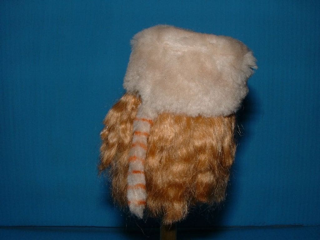
Proof of the pudding, as they say. This specimen can well hold its own. His coonskin hat was made in two pieces from the skin of a stuffed teddy bear. It was hand stitched inside out and glued firmly to his head. The hat was pulled into place and held secure with pins while RC Modeller’s Glue in a syringe was injected via a large bore needle. See next how the tail rings were done.
Photo 14
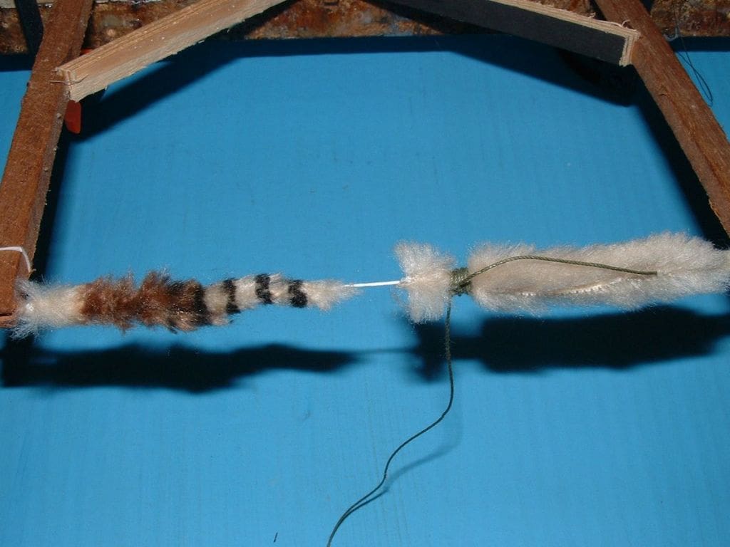
It took some considerable thought and experimenting together with a few naughty words to make the tail rings. The pictures my son had produced from his internet searches showed a range of colours for the rings, dependant apparently upon their individual home territory. The spacing and ring width were however pretty standard with the colours ranging from near black to a sort of reddish rusty hue. A frame was concocted on which to stretch a line across that was then wrapped with strips of leg skin from the poor dissected teddy bear. I bound very tight rings of strong thread, evenly spaced along the fur and then wiped water based paints around the unprotected segments. Eventually I produced a useable version after an afternoon or so of cursing.
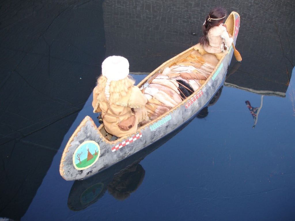
Photo 15
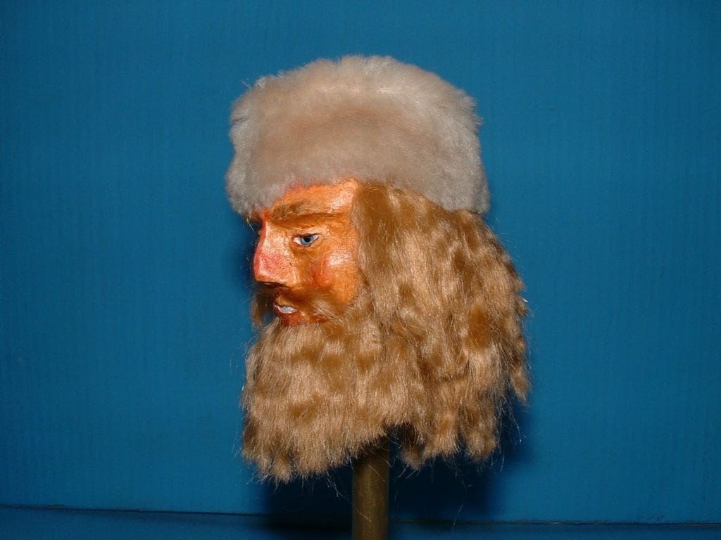
Was it worth it? Well, emphatically yes! Davy Crockett is a bit of a Hollywood myth but nevertheless a colourful character.
Photo 16
Every picture tells a story, so for a change, I’ve nothing much to say. Note how the female’s hair has been pulled down at the side to cover the glue line and also her ear. Earlier I had promised my eldest granddaughter she should do the plait, but after a short go she handed it back, afraid of messing it up.
Photo 17
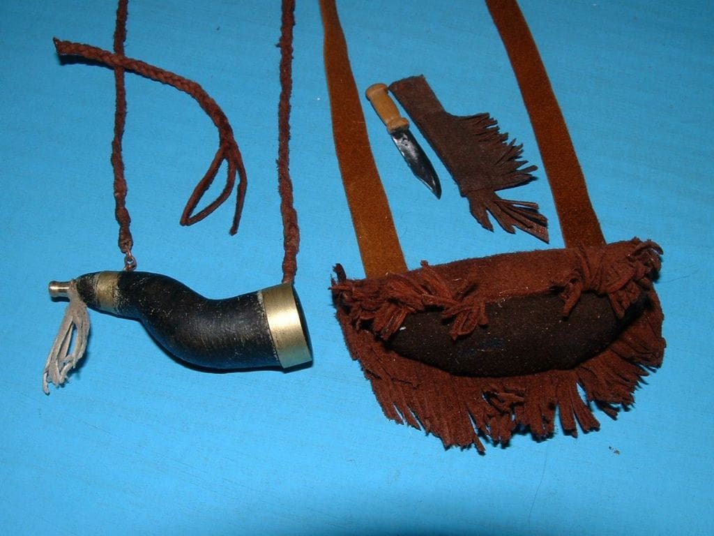
The accoutrements of the serious hunter. On the left side is his powder horn. This was made from Milliput, with slices of brass tube and the brass stopper was turned up from a piece of 3mm rod in the lathe. This horn was number four, as all previous attempts were disasters!
Real examples were a greeny black in colour, the horns having been scrapped as thin as they dared. In this instance the picture does lie a bit, having bleached out the green. Brass rings were belled to shape and installed just before the putty went hard. The light coloured fringe piece, is easy to spot should it be dropped.
On the right hand side in the middle is his Bowie knife. The blade is from a piece of a junior hacksaw and the handle is wood with a total length of just16mm which gives you an idea of scale. His bullet bag is a lump of Milliput covered with thin leather, whilst most of the fringing was done freehand with a new scalpel blade. All fabric to Milliput joints were made with fabric glue.
Why did they have this leather fringing on garments and such things as bags and gun cases? It was not for cosmetic for decorative reasons as might easily be supposed, but was to help dry things out after getting wet. The fringing sucks water from clothes and the extra surface area of the fringes helps the water to evaporate.
His guns I was still experimenting with having some difficulty with scale. His belt was another brain teaser. You’d think it to be simple, but thin leather cannot be stretched without curling at the edges.
Photos 18 and 19
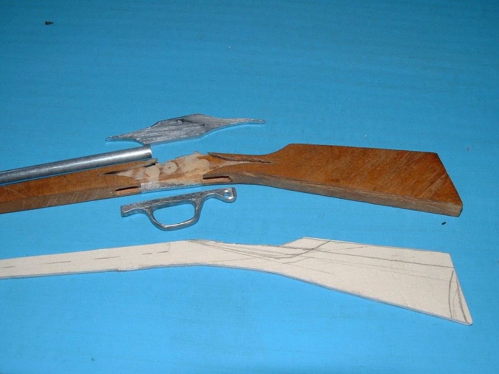
My reference tome for small arms weaponry is called ‘The Illustrated Encyclopedia of Firearms’ and is written by Ian V Hogg. It covers military and civil firearms from the beginning to the present day. Davy Crockett so I thought, might have two weapons, a percussion cap breach loaded gun and a muzzle loader.
Once again, out came the cardboard for patterns that were held in front of him for a size check. Their barrel lengths were the big imponderable as they seemed to be quite long compared to modern rifles.
Now I wanted to incorporate some inlaid metal work. Brass would look very nice but it’s difficult to work and steel? I didn’t fancy that at all, so I settled for alloy. Not authentic I know, but for how many of our models do we use truly authentic material? The timber is satinwood which is simply beautiful to work and looks superb. A friend gave me a piece some time back and I sent a slice to an exotic timber supplier to find out what it was.
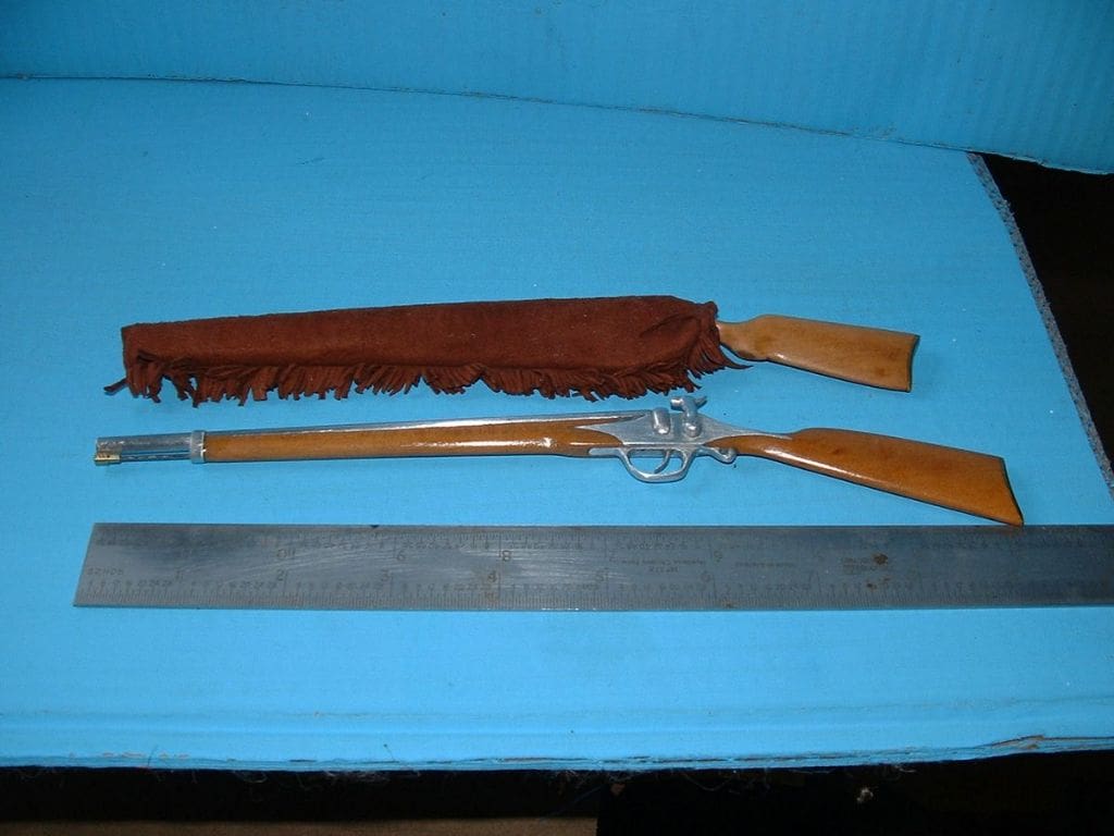
A special, limited edition gun was produced that is nearly 9 inches long. Who can spot it? The cock is on the left hand side which is done for left handed people or so I’ve since been told, and only one person so far at a show has spotted it. The rammer on the piano wire ramrod is turned brass and the other gun in its case is far from complete; just the butt and a length of steel nail shank to lend some weight to it. The nail was painted and wrapped in thin plastic to try and delay rust coming through the case with some fringing to finish it off. The butt plate is brass and proved to be a very satisfying job.
Photos 20 and 21
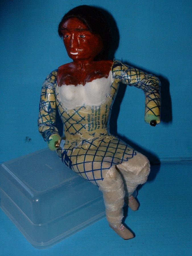
A couple of pictures of the female. In Photo 20 her torso and arms have been padded out with fine foam rubber and wrapped with a yellow duster and then wrapped again with strips of plastic bag and Sellotape. The plastic cover allows her top clothes, in this case a tight fitting buckskin dress to be hauled up and around her shape.
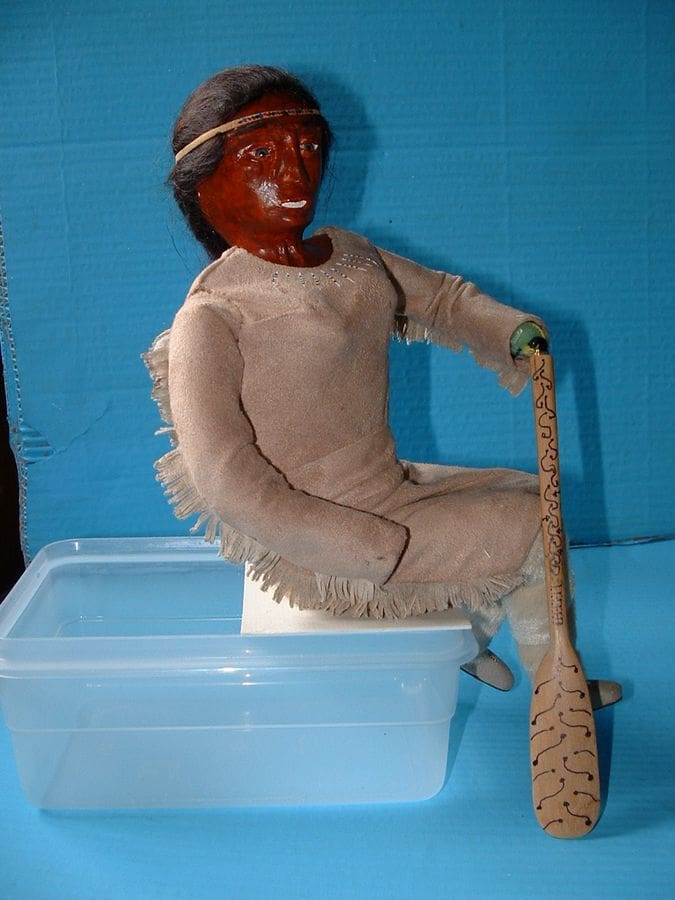
In Photo 21 she has her dress on. The buckskin came from John Lewis Ltd. by way of a half metre of suedette. I sent a sample of what was required to my sister-in-law near Southampton and she went shopping for me.
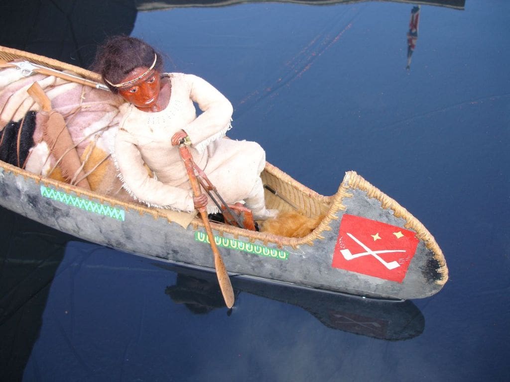
Note her wrapped leggings from some stuff called ponyskin, which is a material, not unlike suedette to look at and her moccasins from suede leather. The paddle made of boxwood is decorated with a copy of a porcupine quill pattern that I saw in one of my reference books. Also, you can just see the ball joint on her left wrist. This will be camouflaged later by a hand, as will the right side, if that makes sense. Also note her body shape which is twisted at the waist as she would most likely be when paddling.
There is some decoration at neck level on her dress and her right arm length was later slightly reduced in length. Making the dress did tax my modelmaking skills quite a bit. It is glued on to her torso with tiny dabs of fabric glue.
The moccasin suede leather came from a friend of my wife. They started out as some very well preserved but unwanted kid leather gloves and it was really a shame to cut them up.
One thing I failed miserably on was a belt for her. I fancied a flat plait from five or so thin strips of leather which proved impossible to make. Now some of you might vaguely recall an incident some years ago, quite widely reported in the media whereby a chap swam across a loch in Scotland, climbed aboard a nuclear submarine and rang the boat’s bell. Well it so happens that he lives not so far away from me and if anybody could help with that belt, then he could.
He loaned me a truly beautiful book from which I determined that flat multi strand plaiting is called ‘Sennit’. I tried, I really did, but the scale beat me. It was so fine it would not stay in place. The book is ‘ The Ashley Book of Knots’, written by Clifford W Ashley, published by Faber and Faber just after WW2. It took the author 11 years to compile. Some examples in the tome include: How to fashion a cat-o-nine tails, or how to fashion slings to hoist an elephant aboard ship.
Deviating a little into the subject of paddling, I’ll tell you about a recent lesson I had from an expert instructor who teaches the military how to paddle efficiently and his recommended method uses ergonomics. Basically the aim is to expend as little effort as possible to achieve the desired distance and it’s called the ‘J Stroke’.
For the execution of the J Stroke, the body of the paddler sits square, facing ahead with the top arm extended at shoulder height and elbow slightly bent but locked solid. This may seem odd, but it gets worse! That arm now becomes a solid and stationary fulcrum. The lower or outboard arm then behaves in an even stranger manner. It exercises a horizontal, sort of capital D movement. It goes out sideways from the canoe side and then the stroke part is parallel with the canoe side. Apparently it’s less tiring and is also far quieter with no splashing or dripping from the paddle. However after all of this, I’m now told that the J Stroke is old-hat and is superseded by a newer method!
Photo 22
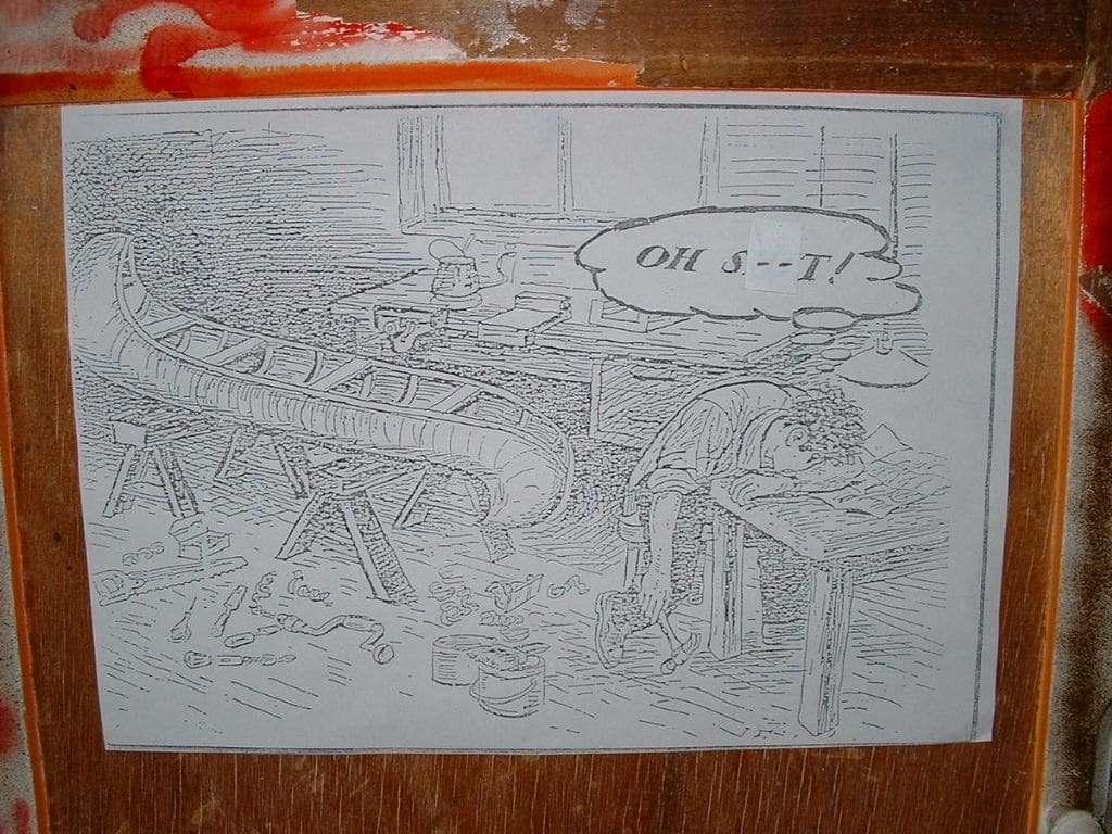
A bit of frivolity, but some of you at least might like to share the joke. I have no earthly idea who to ask for permission to reproduce this picture, but it does tell a thousand words and now the serious bit.
Do you know why the pointy stems are built onto the hull? When canoe travellers, went ashore at night, they turned the canoes over bottoms up onto those points at each end and put a forked stick under one gunnel so it leant over facing the weather. Then the crew slept under it and nose-to-tail. Thus no need for a tent or such like.
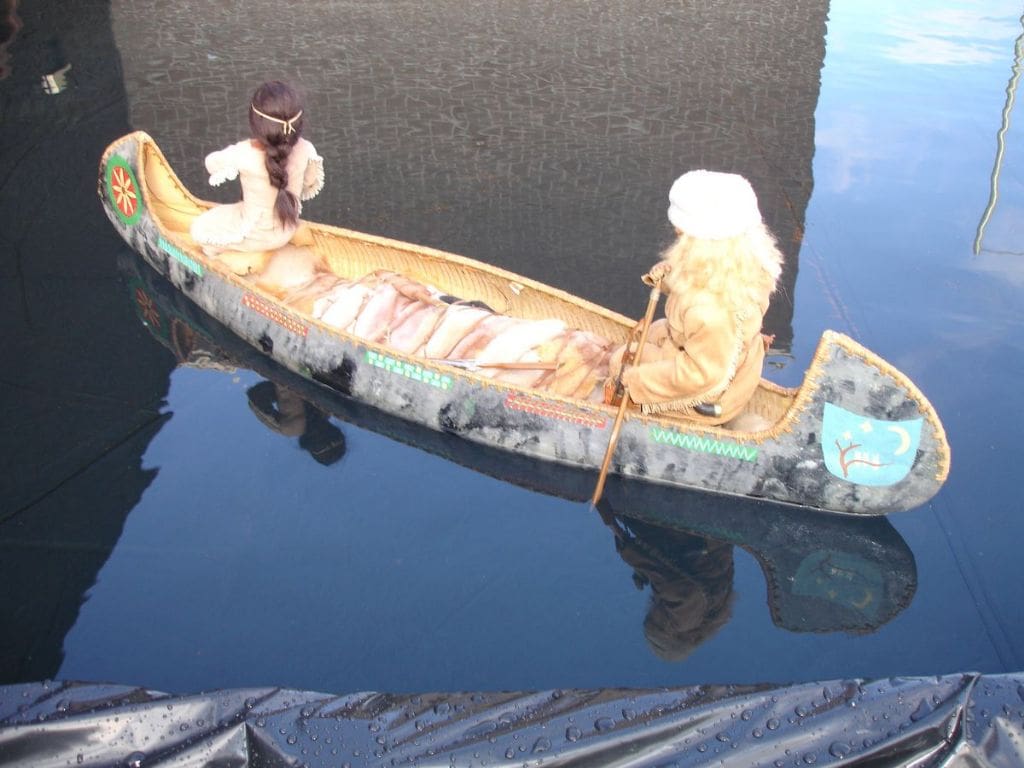
Photo 23
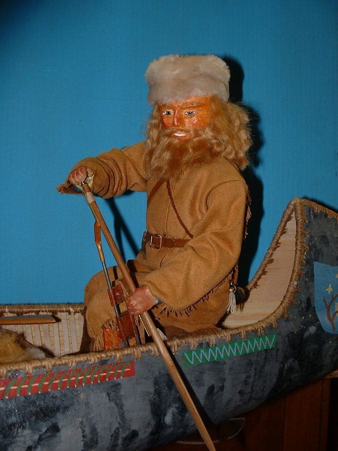
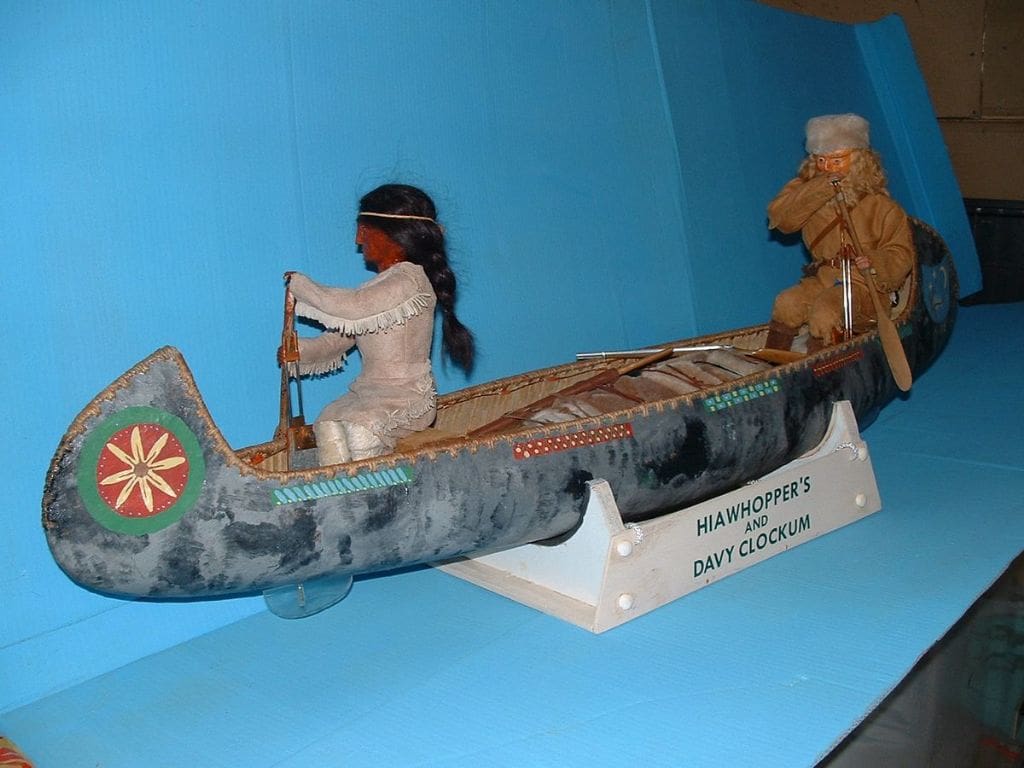
Davy Crockett is now bolted into the hull. Note the twin crank rods that stop any twist tendency and subsequent jamming. It’s a shame for both of the crew could have done with rather more lift on the cranks, but it was not possible because I had deepened the hull as much as I’d dared, to accommodate the crank.
Photo 24
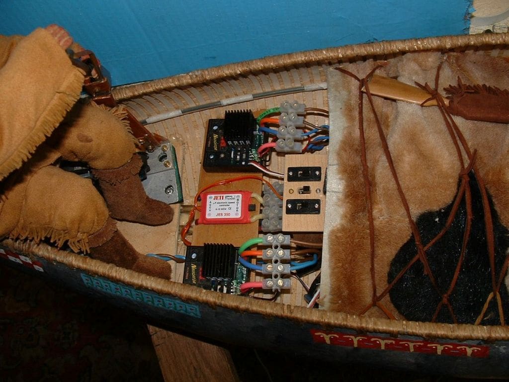
In the middle can be seen the electrical department which is normally covered by a thin fibreglass stiffened piece of cardboard. The switches and block connectors give an idea of scale. It was deliberately lumpy shaped to suggest something underneath, then covered with pieces of fur pelt obtained from some unwanted stuffed toys. You can see some on the right with a criss-cross leather thong lashing. Davy’s boots can also be seen and are made from litho plate and Milliput, then covered with thin suede leather, glued using fabric glue. One of his guns can also just be seen.
The binding around the gunnel can be seen (and also in Photo 23). It was done with normal brown parcel string and took ages to do. Two or three coats of clear matt polyurethane varnish was finally applied to protect the string and lay the straggly bits down. It seems that individual canoe builders adopted their own pattern for the binding which became a sort of trademark. In this instance I chose a style would serve my purpose.
Photo 25
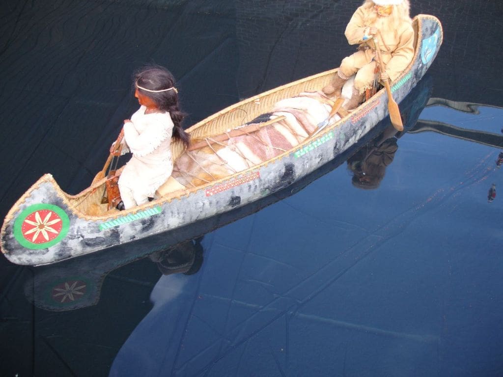
Well, it took nearly a year and was not the easiest off projects, with many delays for one thing or another which all had to be worked around, but a pleasing conclusion nevertheless.
The model performs better without any wind as he and she at each end act rather like uncontrolled sails. Under the hull can be seen one of the two perspex rudders. Yes, one has to cheat a bit to get the canoe to steer! They allow for fairly good steering control, but not in windy conditions.
Finally, the amount of ballast required was 8 1/2 lbs, so I wasn’t far out from my earlier estimate of 9 lbs.
Regular readers will have seen Mike’s recent articles in May 2008 and July 2009 MB. Making models that really do row or paddle are a mental and modelling challenge, but very satisfying when they work properly and are finished. They make a change from the traditional scale model with propellers or paddle wheels and do require some basic engineering input and ingenuity to build. Mike’s models always attract interest when displayed at various events in the UK. He is to be particularly congratulated on his work with figures – Editor.